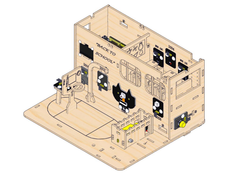
Installation of the Smart School
2.1 Teaching Building
1. Installation of the Teaching Building
Step 1: Install ESP32 board
1.1
Required parts
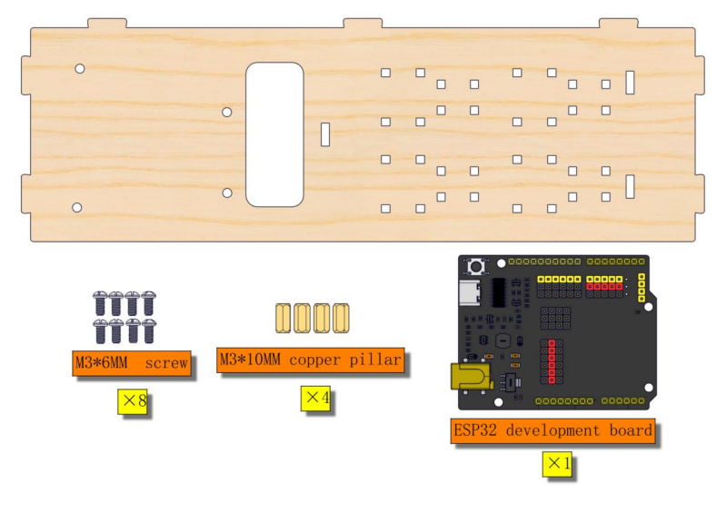
1.2
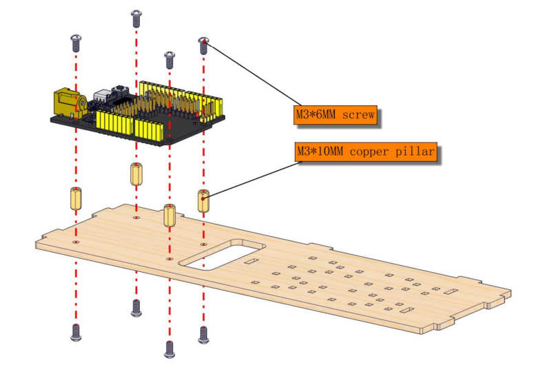
1.3
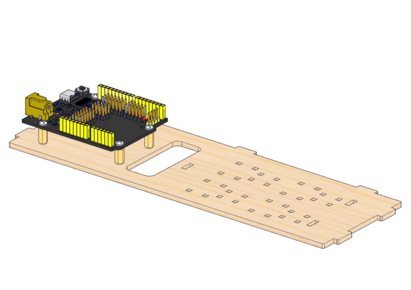
1.4
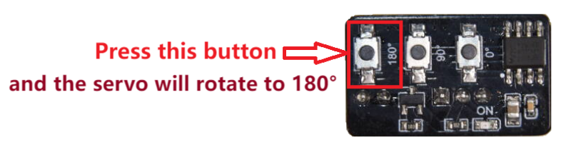
Note: The servo angle needs to be calibrated. Follow the instructions shown below.
Required parts
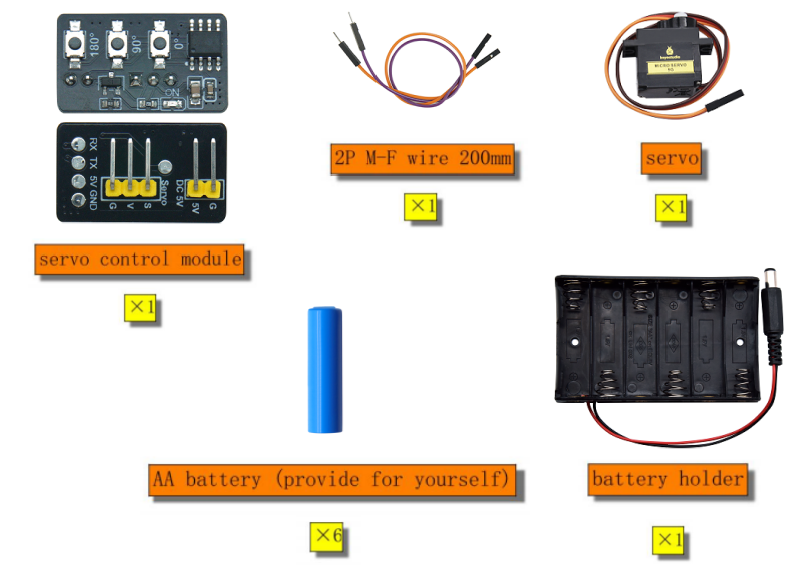
Required wire:
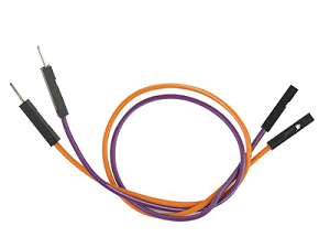
2PIN M-F DuPont wire (random color)
servo |
servo control module |
|---|---|
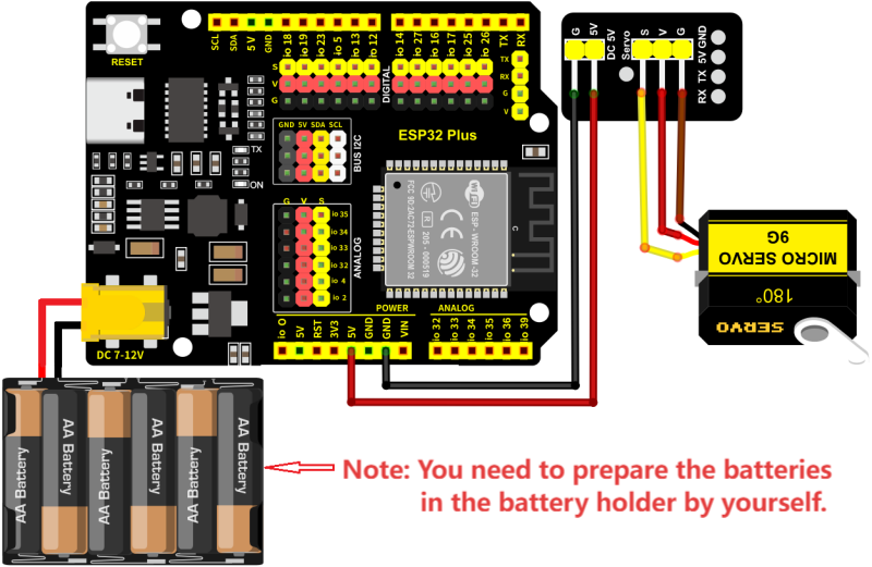
orange wire |
S |
red wire |
V |
brown wire |
G |
servo control module |
main control board |
|---|---|
5V |
5V |
G |
GND |
Wiring diagram:
After servo calibration, please remove all the wiring.
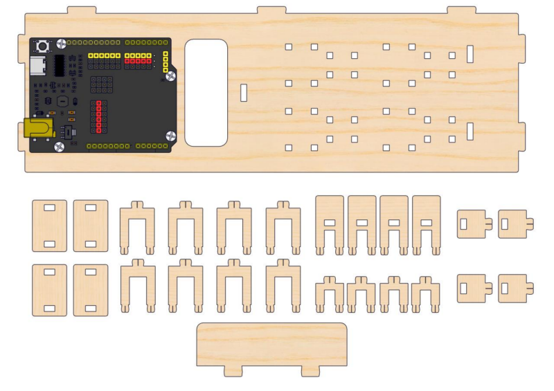
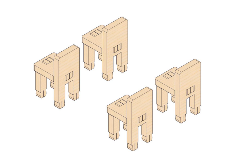
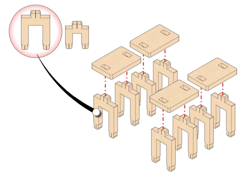
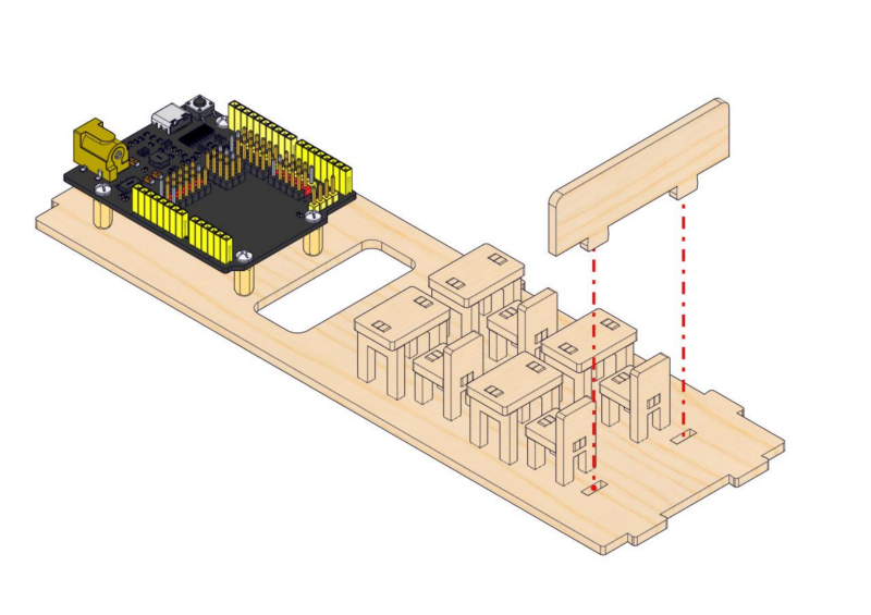
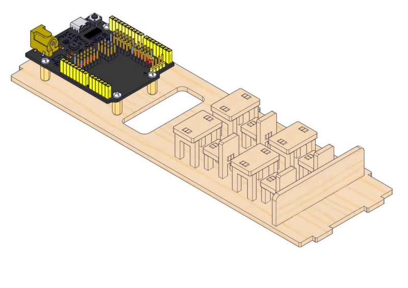
Step 2: Assemble desks and chairs
2.1
Required parts
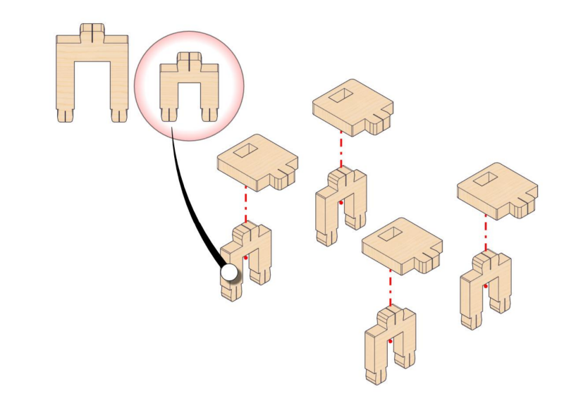
2.2
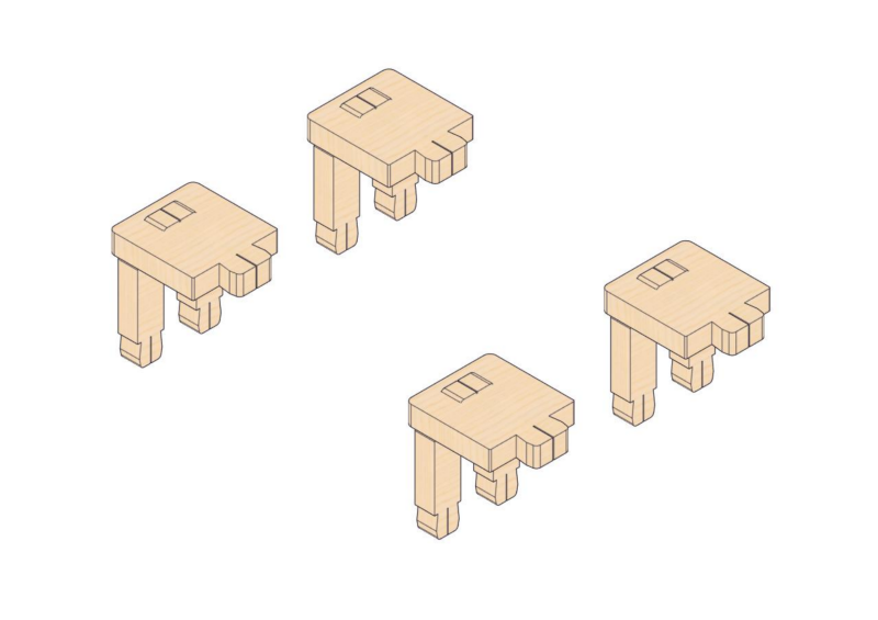
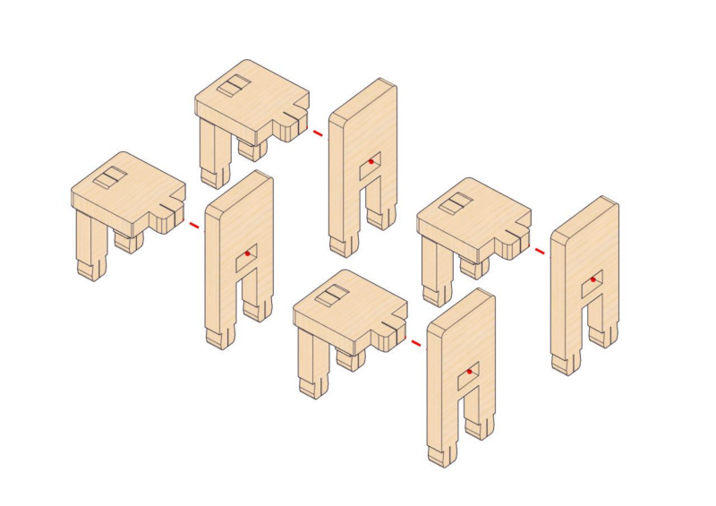
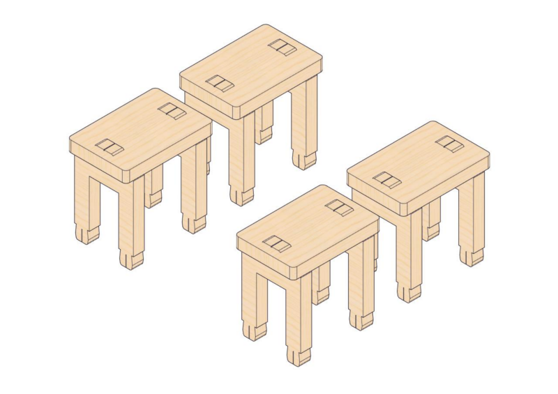
2.3
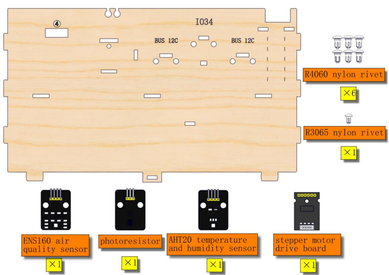
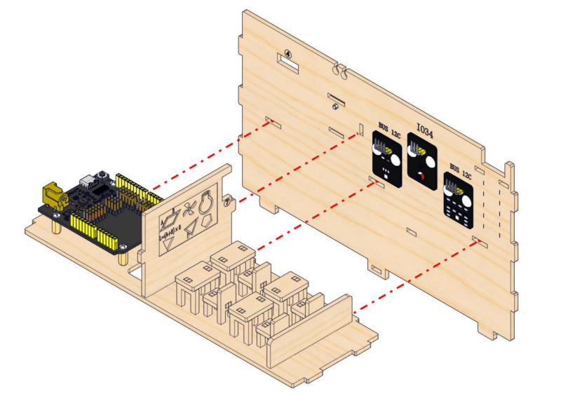
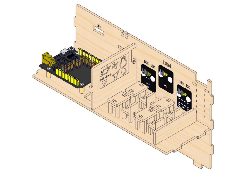
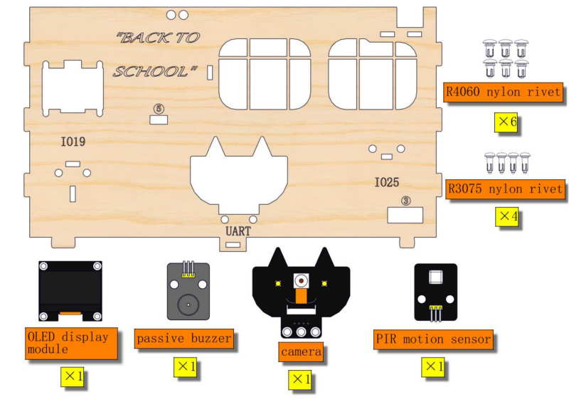
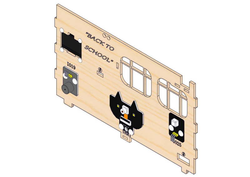
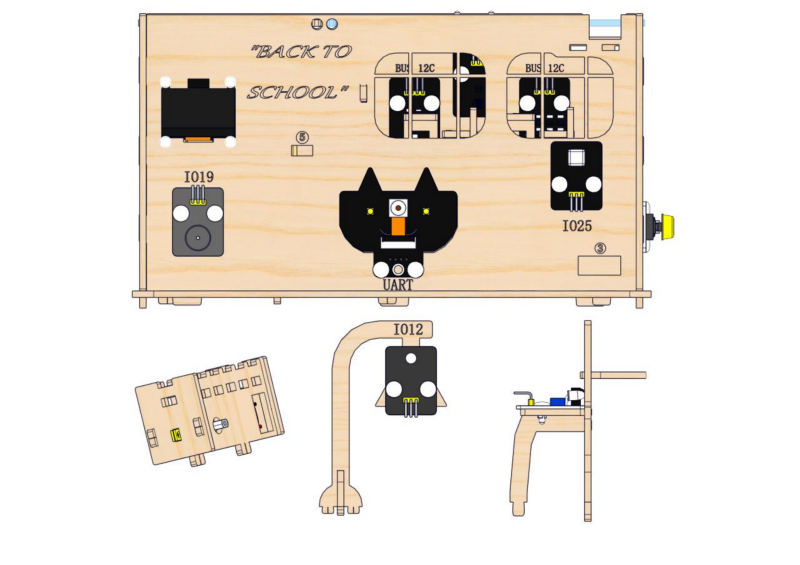
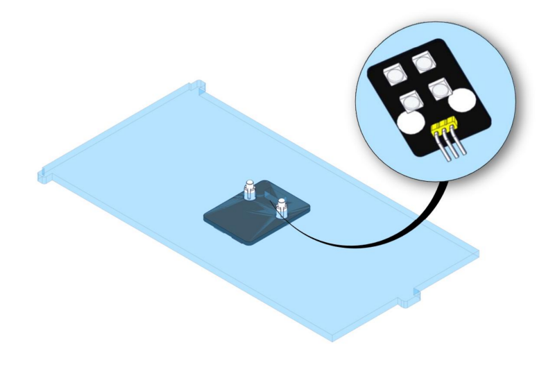
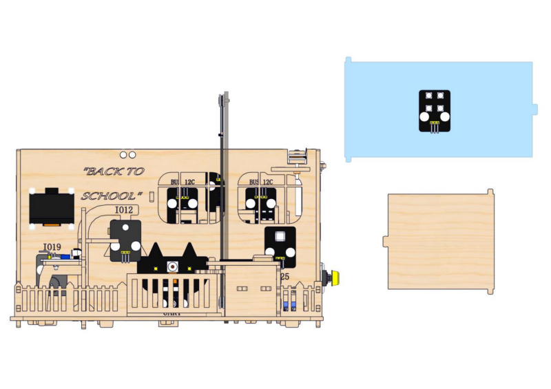
Step 3: Install modules on the back wall
3.1
Required parts
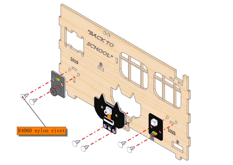
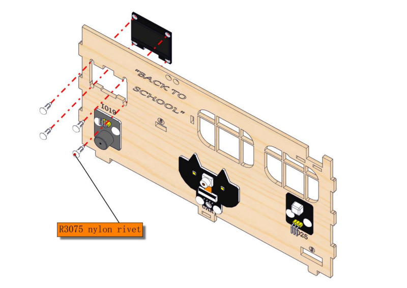
3.2
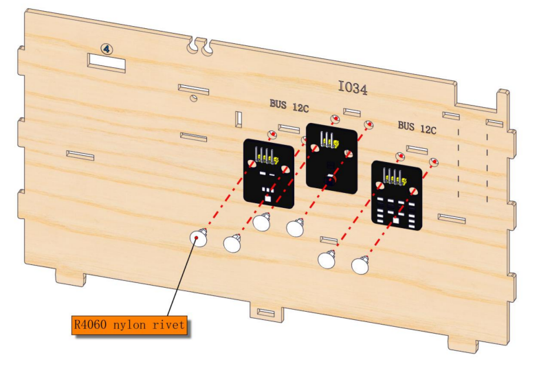
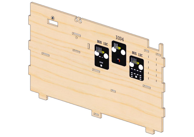
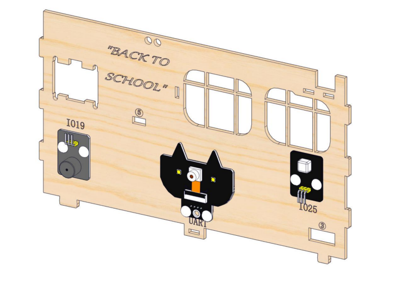
3.3
Step 4: Install the classroom blackboard
4.1
Required parts
4.2
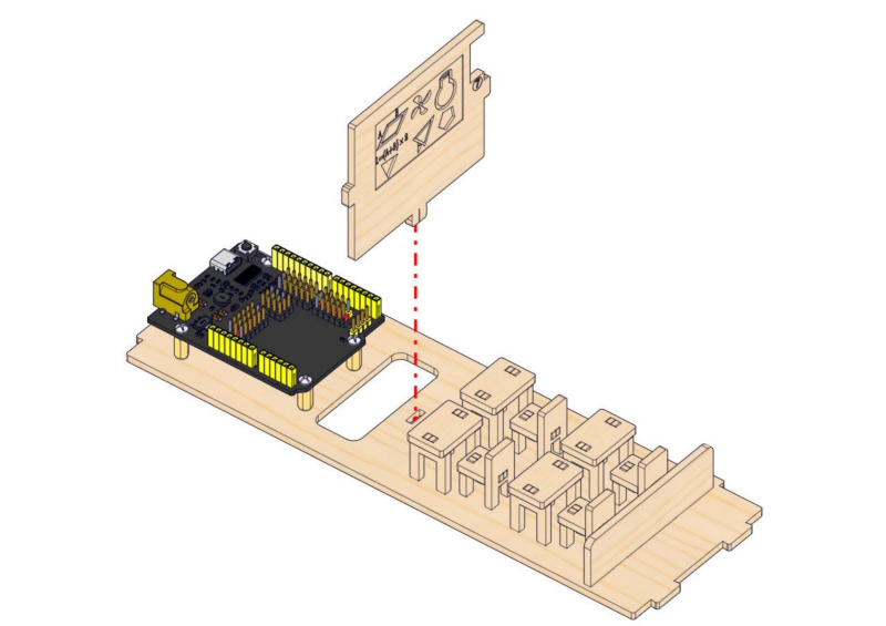
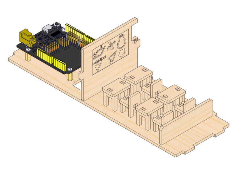
4.3
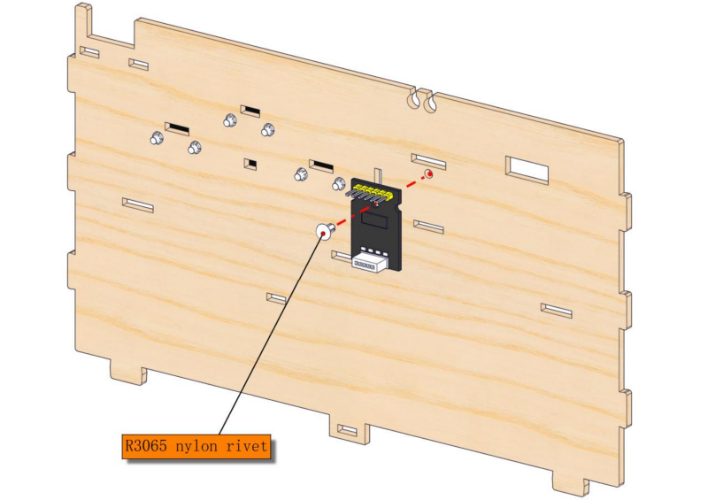
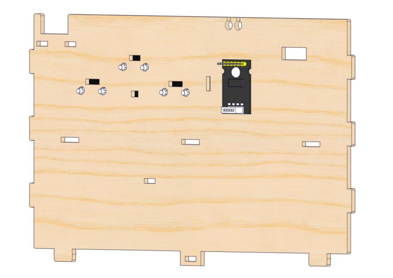
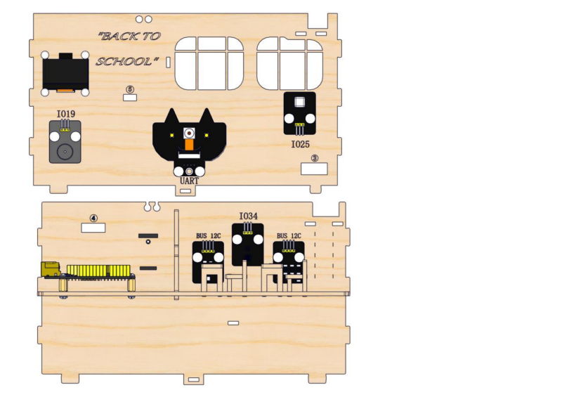
Step 5: Install modules on the front wall
5.1
Required parts
5.2
5.3
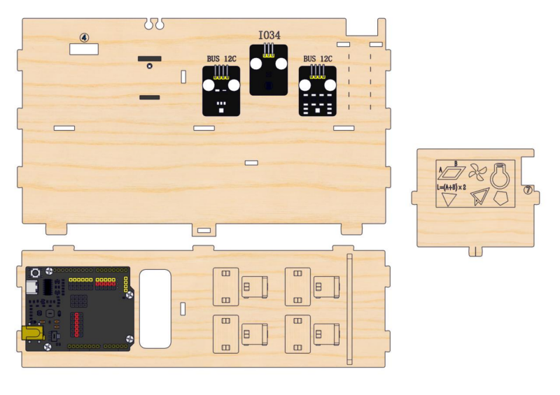
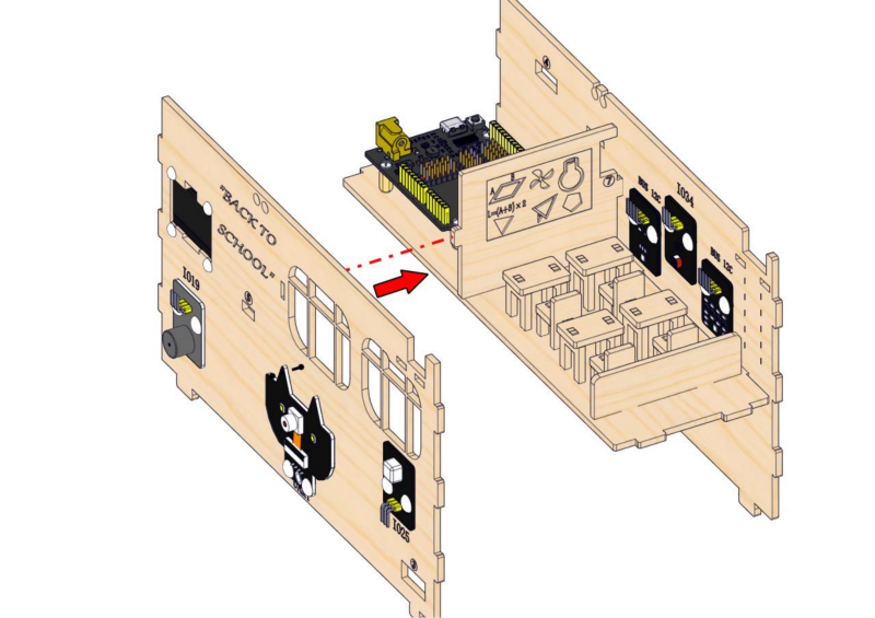
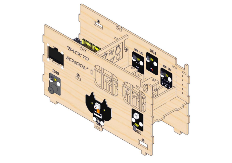
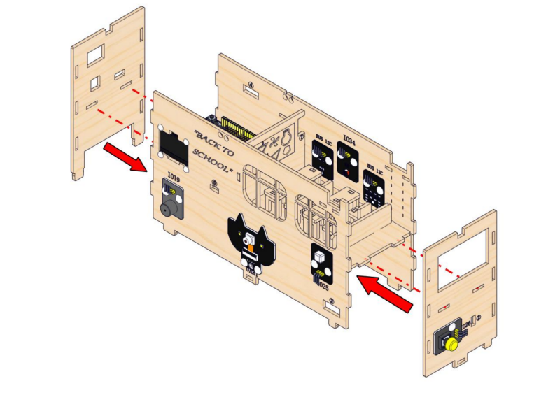
Step 6: Assemble walls
6.1
Required parts
6.2
Step 7: Assemble two side walls, install the button module
7.1
Required parts
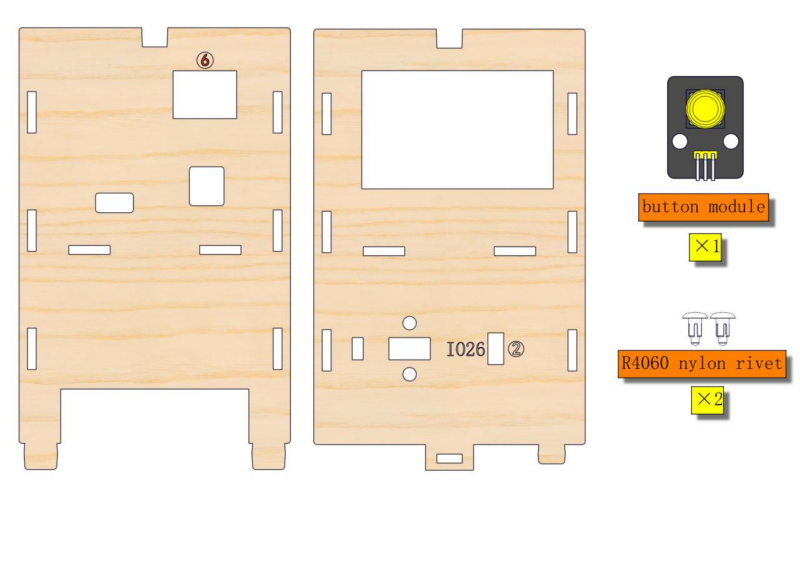
7.2
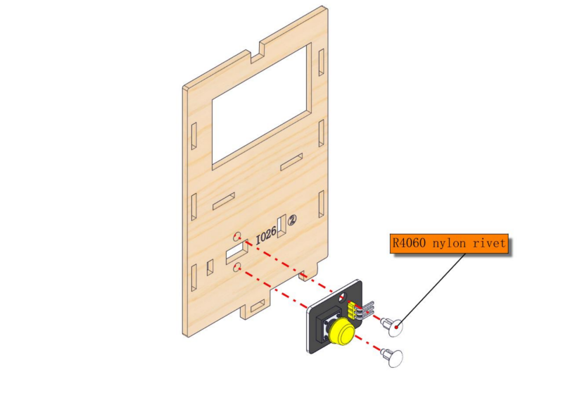
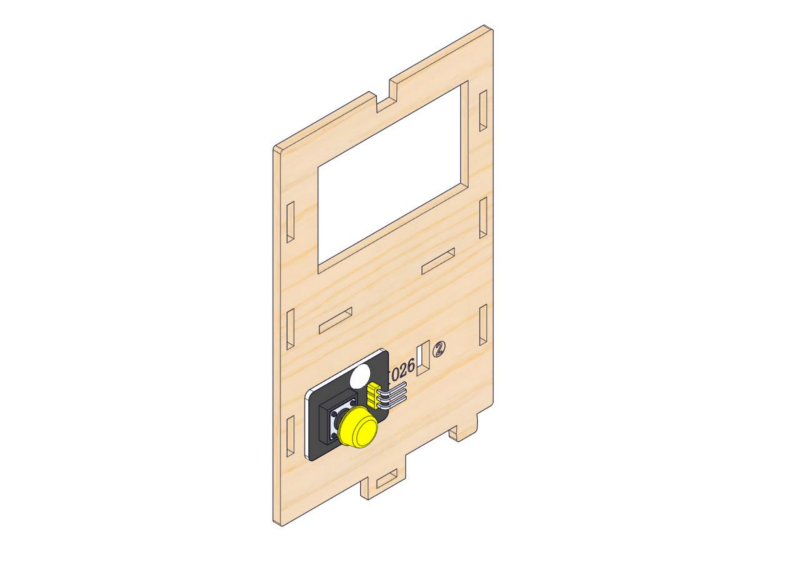
7.3
2. Wiring of Teaching Building
Step 8: Teaching building wiring
8.1
Please connect the wires in the following order. When connecting, please distinguish the color of the wires.
# |
Module |
Wire |
ESP32 board pin |
|---|---|---|---|
1 |
camera |
4PIN (black-red-yellow-white) |
|
2 |
button module |
3PIN 250mm |
IO26 |
3 |
PIR motion sensor |
3PIN 250mm |
IO25 |
4 |
stepper motor drive board |
6PIN 200mm |
|
5 |
white LED module |
3PIN 200mm |
IO12 |
6 |
motor drive board |
4PIN 350mm (black-red-blue-green) |
IO5(INA) IO13(INB) |
7 |
passive buzzer |
3PIN 200mm |
IO19 |
8 |
obstacle avoidance sensor |
3PIN 200mm |
IO18 |
9 |
OLED module |
4PIN 200mm (black-red-blue-green) |
|
10 |
ENS160 air quality sensor |
4PIN 200mm (black-red-blue-green) |
BUS 12C |
11 |
AHT20 temperature |
4PIN 200mm (black-red-blue-green) |
BUS 12C |
12 |
RFID module |
4PIN 400mm (black-red-blue-green) |
BUS 12C |
13 |
photoresistor |
3PIN 200mm |
IO34 |
14 |
RGB LED module |
3PIN 200mm |
IO4 |
8.2
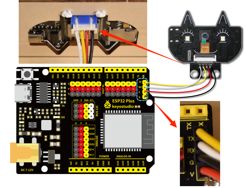
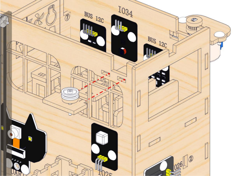
Connect the module to the ESP32 main control board via the wire as shown in the diagram.
Module |
Wire |
Corresponding pin |
|---|---|---|
camera |
4PIN (black-red-yellow-white) |
UART |
The wire needed here:

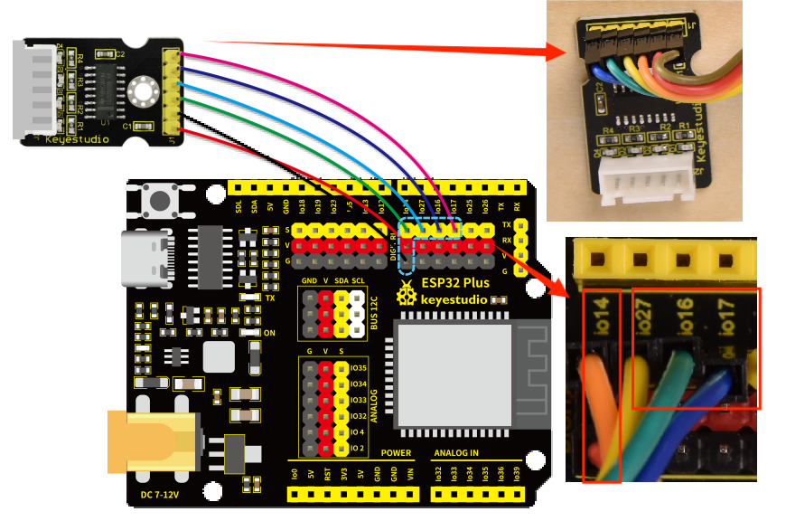
When wiring, connect the 4pin header to the camera, and pass 4 female headers through hole 1 and then connect them to the ESP32 main board.
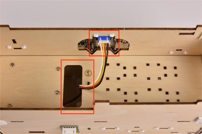
When connecting to the main board, please distinguish the colors of wires.
camera |
Wire color |
ESP32 board pin |
|---|---|---|
V |
Red wire |
V |
G |
Black wire |
G |
TX |
Yellow wire |
RX |
RX |
White wire |
TX |
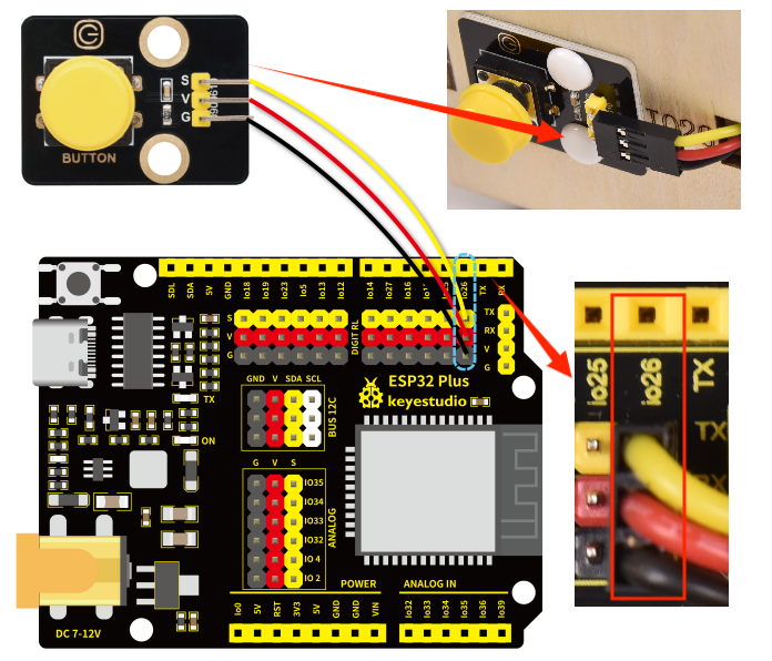
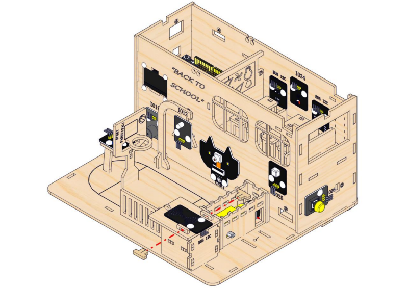
8.3
Connect the module to the ESP32 main control board via the wire as shown in the diagram.
Module |
Wire |
Corresponding pin |
|---|---|---|
button module |
3PIN 250mm |
IO26 |
The wire needed here:

When wiring, connect one end of the wire to the single-channel button module, and pass the other end successively through Hole 2 and Hole 1, and then connect it to the ESP32 main board.
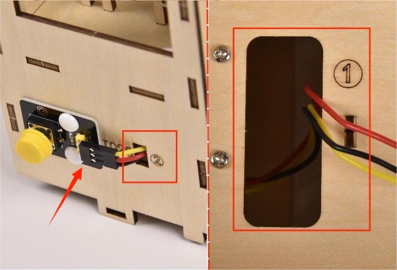
When connecting to the main board, please distinguish the color of the wires.
Module |
Wire color |
ESP32 board pin |
|---|---|---|
V |
Red wire |
V |
G |
Black wire |
G |
S |
Yellow wire |
IO26 |
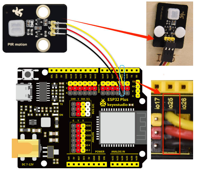
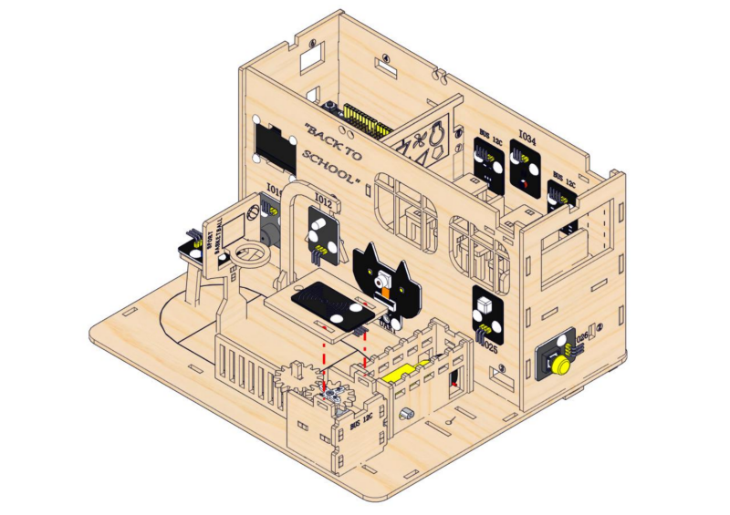
8.4
Connect the module to the ESP32 main control board via the wire as shown in the diagram.
Module |
Wire |
Corresponding pin |
|---|---|---|
PIR motion sensor |
3PIN 250mm |
IO25 |
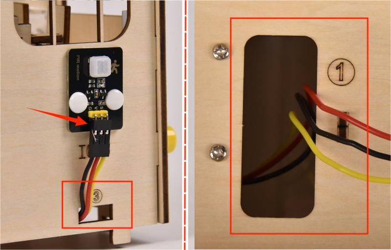
The wire needed here:

When wiring, connect one end of the wire to the PIR motion sensor, and pass the other end successively through Hole 3 and Hole 1, and then connect it to the ESP32 main board.
When connecting to the main board, please distinguish the color of the wires.
Module |
Wire color |
ESP32 board pin |
|---|---|---|
V |
Red wire |
V |
G |
Black wire |
G |
S |
Yellow wire |
IO25 |
8.5
Connect the module to the ESP32 main control board via the wire as shown in the diagram.
Module |
Wire |
Corresponding pin |
|---|---|---|
stepper motor drive board |
6PIN 200mm |
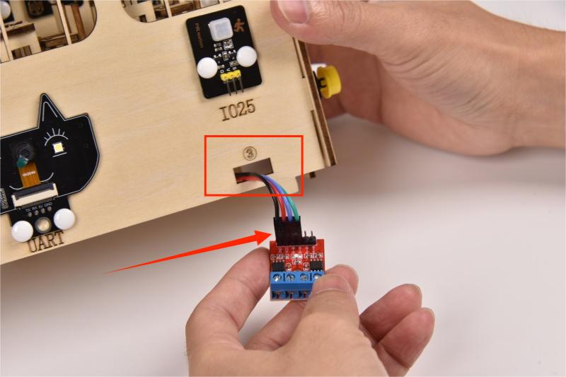
The wire needed here:

⚠️ Please note that there is no need to pay attention to the color of the 6-pin wire. Make sure that the module wiring corresponds to that of main board.
When wiring, connect one end of the wire to the stepper motor drive board, and pass the other end through Hole 4, and then connect it to the ESP32 main board.
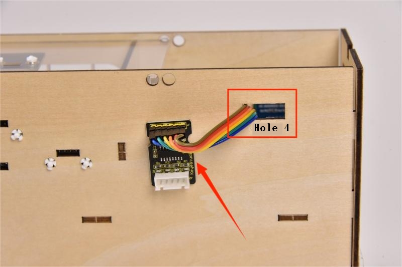
Please connect to the main control board in the order of the wiring on the stepper motor drive board as shown below:
8.6
Connect the module to the ESP32 main control board via the wire as shown in the diagram.
Module |
Wire |
Corresponding pin |
|---|---|---|
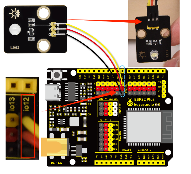
white LED module |
3PIN 200mm |
IO12 |
The wire needed here:

When wiring, connect one end of the wire to the white LED module, and pass the other end through Hole 5, and then connect it to the ESP32 main board.
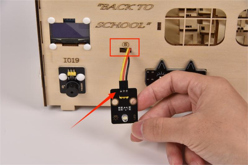
When connecting to the main board, please distinguish the colors of the wires.
Module |
Wire color |
ESP32 board pin |
|---|---|---|
V |
Red wire |
V |
G |
Black wire |
G |
S |
Yellow wire |
IO12 |
8.7
Connect the module to the ESP32 main control board via the wire as shown in the diagram.
Module |
Wire |
Corresponding pin |
|---|---|---|
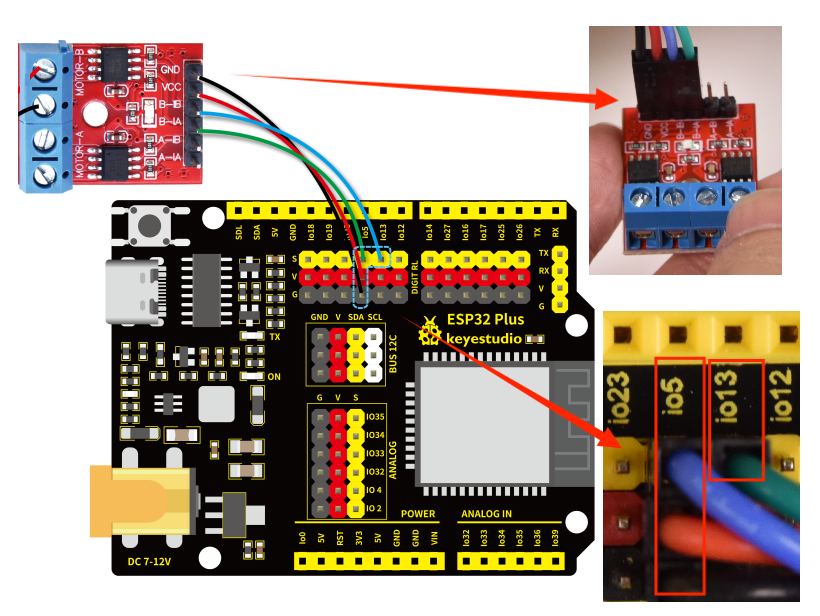
motor drive board |
4PIN 350mm (black-red-blue-green) |
IO5、IO13 |
The wire needed here:

When wiring, connect the 4pin end of the wire to the motor drive board, and pass 4 female headers successively through Hole 3 and Hole 1, and then connect them to the ESP32 main board.
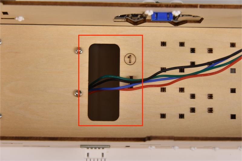
When connecting to the main board, please distinguish the colors of the wires.
Module |
Wire color |
ESP32 board pin |
|---|---|---|
GND |
Black wire |
G |
VCC |
Red wire |
V |
B-IB |
Green wire |
IO13 |
B-IA |
Blue wire |
IO5 |
8.8
Connect the module to the ESP32 main control board via the wire as shown in the diagram.
Module |
Wire |
Corresponding pin |
|---|---|---|
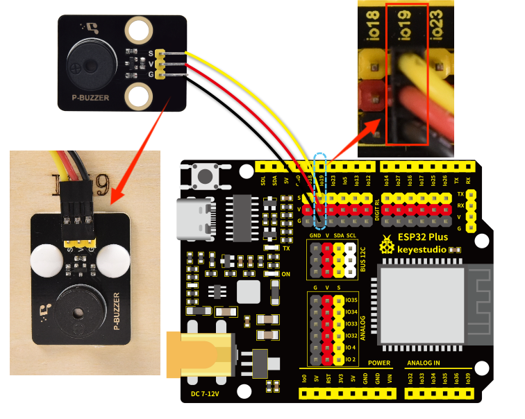
passive buzzer |
3PIN 200mm |
IO19 |
The wire needed here:

When wiring, connect one end of the wire to the passive buzzer, and pass the other end through Hole 6, and then connect it to the ESP32 main board.
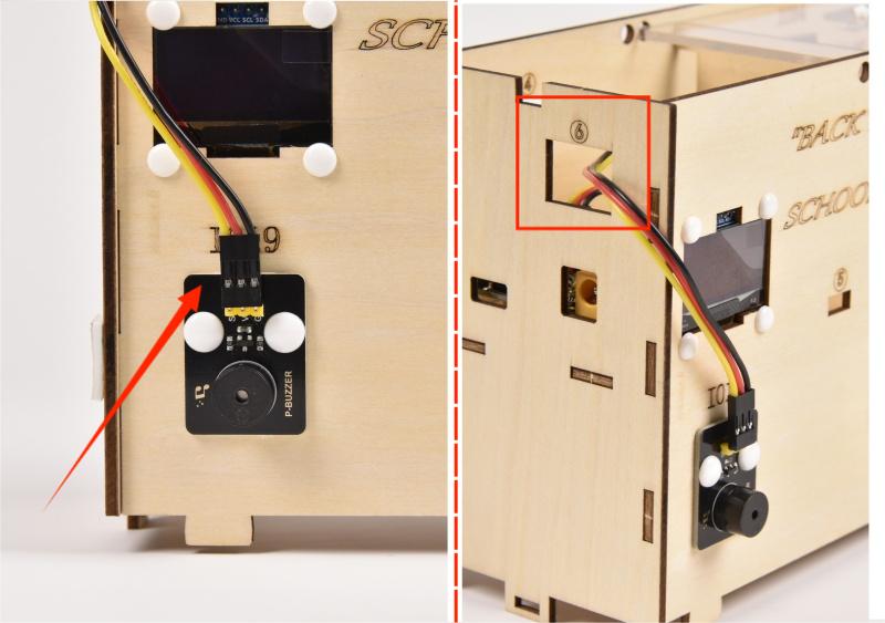
When connecting to the main board, please distinguish the color of the wires.
Module |
Wire color |
ESP32 board pin |
|---|---|---|
V |
Red wire |
V |
G |
Black wire |
G |
S |
Yellow wire |
IO19 |
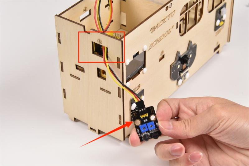
8.9
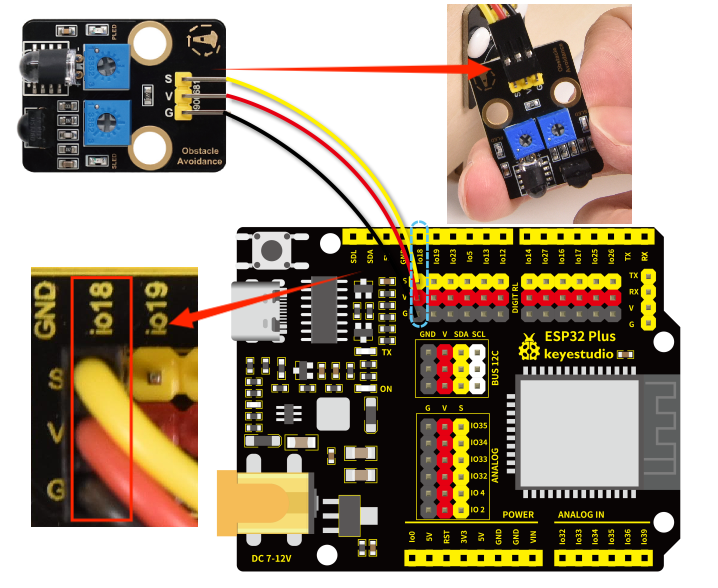
Connect the module to the ESP32 main control board via the wire as shown in the diagram.
Module |
Wire |
Corresponding pin |
|---|---|---|
obstacle avoidance sensor |
3PIN 200mm |
IO18 |
The wire needed here:

When wiring, connect one end of the wire to the obstacle avoidance sensor, and pass the other end through Hole 6, and then connect it to the ESP32 main board.
When connecting to the main board, please distinguish the color of the wires.
Module |
Wire color |
ESP32 board pin |
|---|---|---|
V |
Red wire |
V |
G |
Black wire |
G |
S |
Yellow wire |
IO18 |
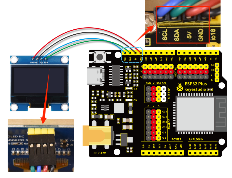
8.10
Connect the module to the ESP32 main control board via the wire as shown in the diagram.
Module |
Wire |
Corresponding pin |
|---|---|---|
OLED display |
4PIN 200mm (black-red-blue-green) |
BUS 12C |
The wire needed here:

When wiring, connect 4pin end of the wire to the OLED display, and connect 4 female headers to the ESP32 main board.
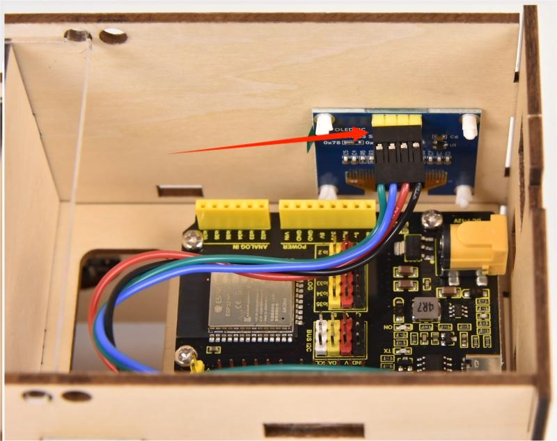
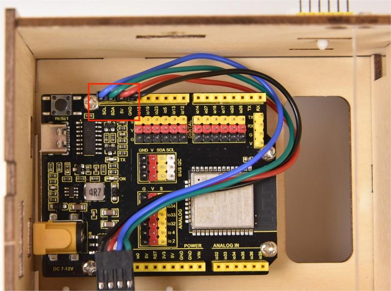
When connecting to the main board, please distinguish the color of the wires.
Module |
Wire color |
ESP32 board pin |
|---|---|---|
GND |
Red wire |
GND |
VCC |
Black wire |
VCC |
SCL |
Blue wire |
SCL |
SDA |
Green wire |
SDA |
Note that the sequence of SCL and SDA on the main board is reversed to that of the OLED module.
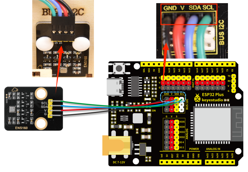
8.11
Connect the module to the ESP32 main control board via the wire as shown in the diagram.
Module |
Wire |
Corresponding pin |
|---|---|---|
ENS160 air quality sensor |
4PIN 200mm (black-red-blue-green) |
BUS 12C |
The wire needed here:

When wiring, connect one end of the wire to the ENS160 air quality sensor, and pass the other end through Hole 7, and then connect it to the ESP32 main board.
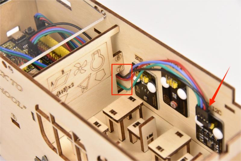
When connecting to the main board, please distinguish the color of the wires.
Module |
Wire color |
ESP32 board pin |
|---|---|---|
GND |
Black wire |
GND |
VCC |
Red wire |
V |
SDA |
Blue wire |
SDA |
SCL |
Green wire |
SCL |
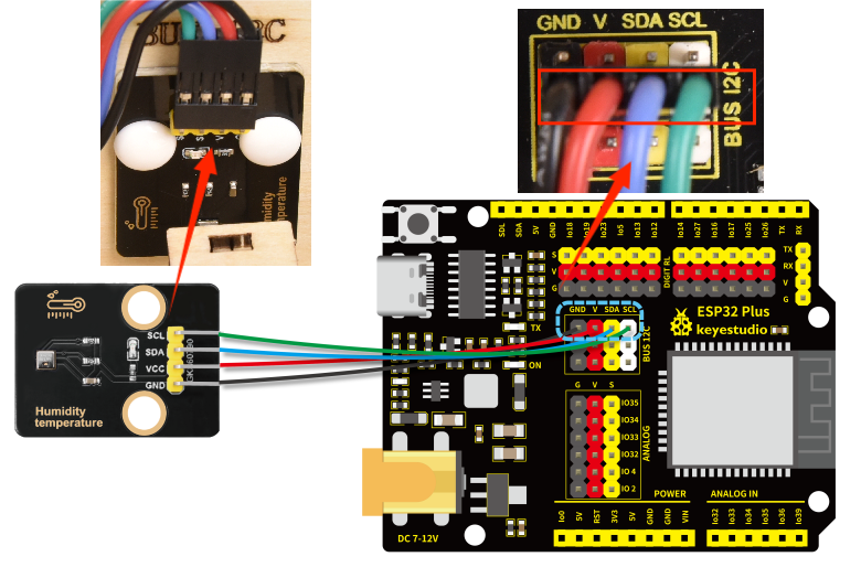
8.12
Connect the module to the ESP32 main control board via the wire as shown in the diagram.
Module |
Wire |
Corresponding pin |
|---|---|---|
AHT20 temperature and humidity sensor |
4PIN 200mm (black-red-blue-green) |
BUS 12C |
The wire needed here:

When wiring, connect one end of the wire to the AHT20 temperature and humidity sensor, and pass the other end through Hole 7, and then connect it to the ESP32 main board.
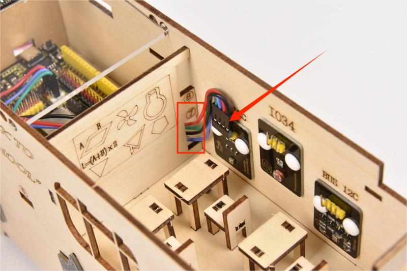
When connecting to the main board, please distinguish the color of the wires.
Module |
Wire color |
ESP32 board pin |
|---|---|---|
GND |
Black wire |
GND |
VCC |
Red wire |
V |
SDA |
Blue wire |
SDA |
SCL |
Green wire |
SCL |
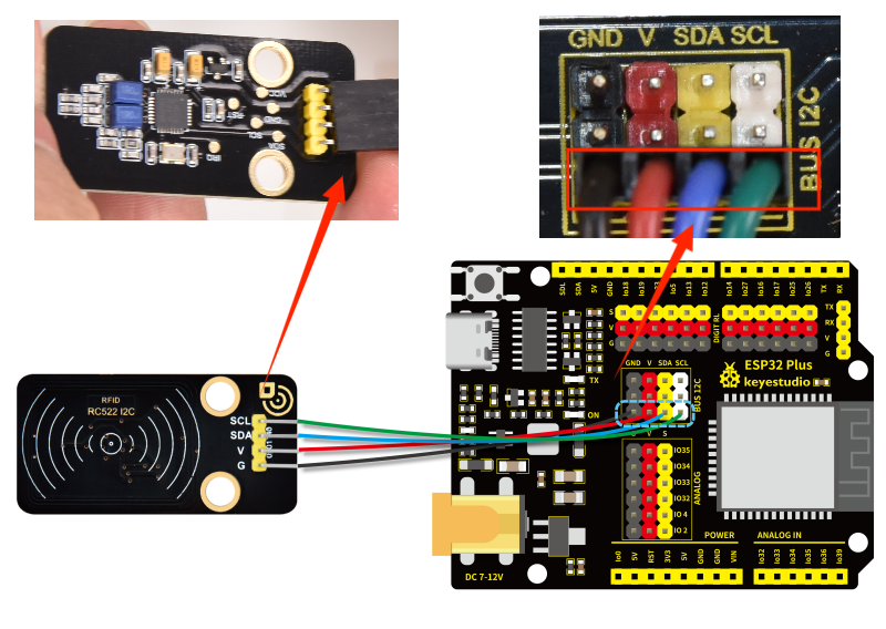
8.13
Connect the module to the ESP32 main control board via the wire as shown in the diagram.
Module |
Wire |
Corresponding pin |
|---|---|---|
RFID module |
4PIN 400mm (black-red-blue-green) |
BUS 12C |
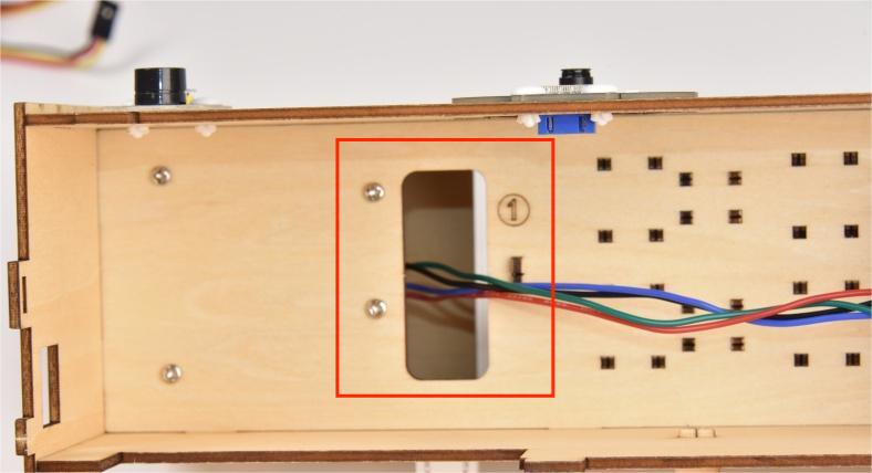
The wire needed here:

When wiring, connect one end of the wire to the RFID module, and pass the other end successively through Hole 3 and Hole 1, and then connect it to the ESP32 main board.
When connecting to the main board, please distinguish the color of the wires.
Module |
Wire color |
ESP32 board pin |
|---|---|---|
GND |
Black wire |
GND |
VCC |
Red wire |
V |
SDA |
Blue wire |
SDA |
SCL |
Green wire |
SCL |
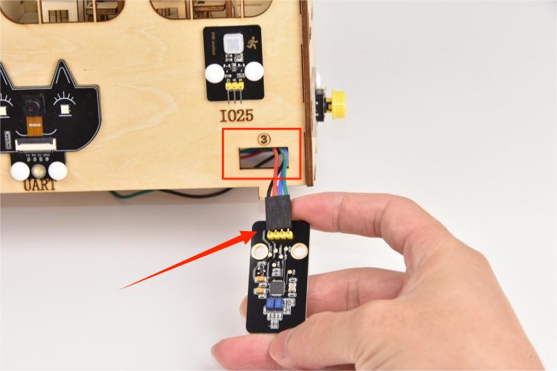
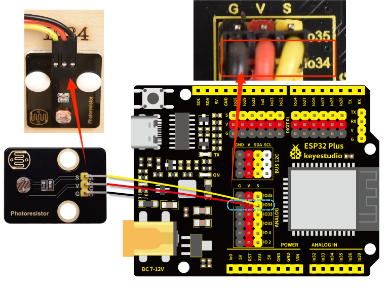
8.14
Connect the module to the ESP32 main control board via the wire as shown in the diagram.
Module |
Wire |
Corresponding pin |
|---|---|---|
photoresistor |
3PIN 200mm |
IO34 |
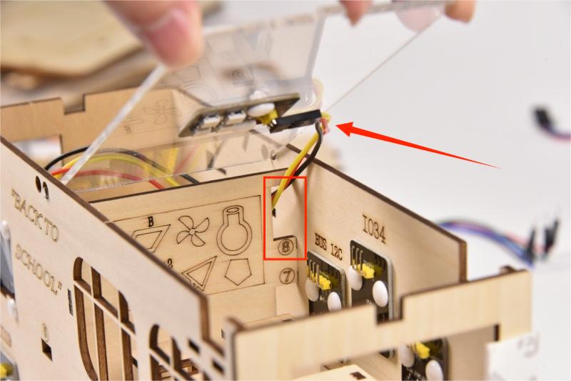
The wire needed here:

When wiring, connect one end of the wire to the photoresistor, and pass the other end through Hole 8, and then connect it to the ESP32 main board.
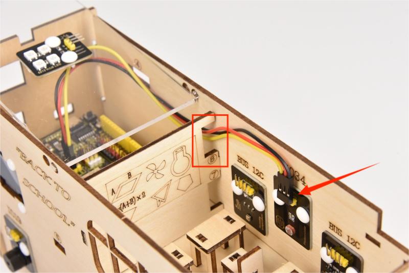
When connecting to the main board, please distinguish the color of the wires.
Module |
Wire color |
ESP32 board pin |
|---|---|---|
V |
Red wire |
V |
G |
Black wire |
G |
S |
Yellow wire |
IO34 |
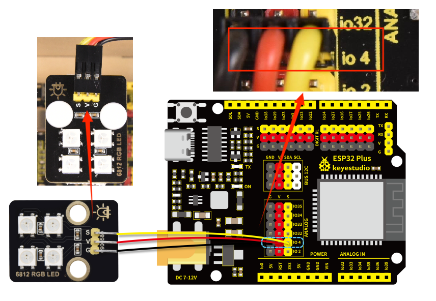
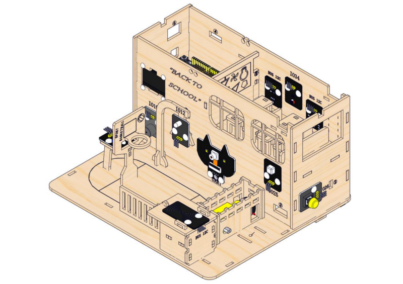
8.15
Connect the module to the ESP32 main control board via the wire as shown in the diagram.
Module |
Wire |
Corresponding pin |
|---|---|---|
RGB module |
3PIN 200mm |
IO4 |
The wire needed here:

When wiring, connect one end of the wire to the RGB module, and pass the other end through Hole 8, and then connect it to the ESP32 main board.
When wiring, please distinguish the color of the wire.
Module |
Wire color |
ESP32 board pin |
|---|---|---|
V |
Red wire |
V |
G |
Black wire |
G |
S |
Yellow wire |
IO4 |
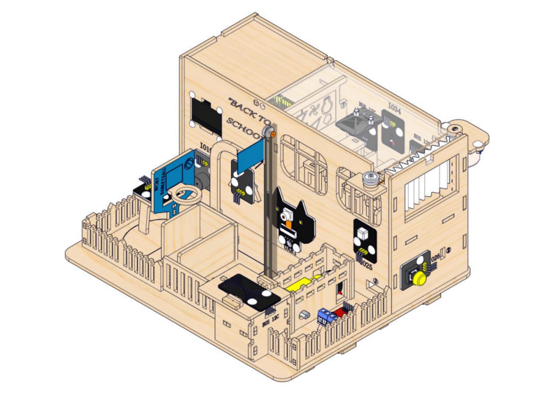
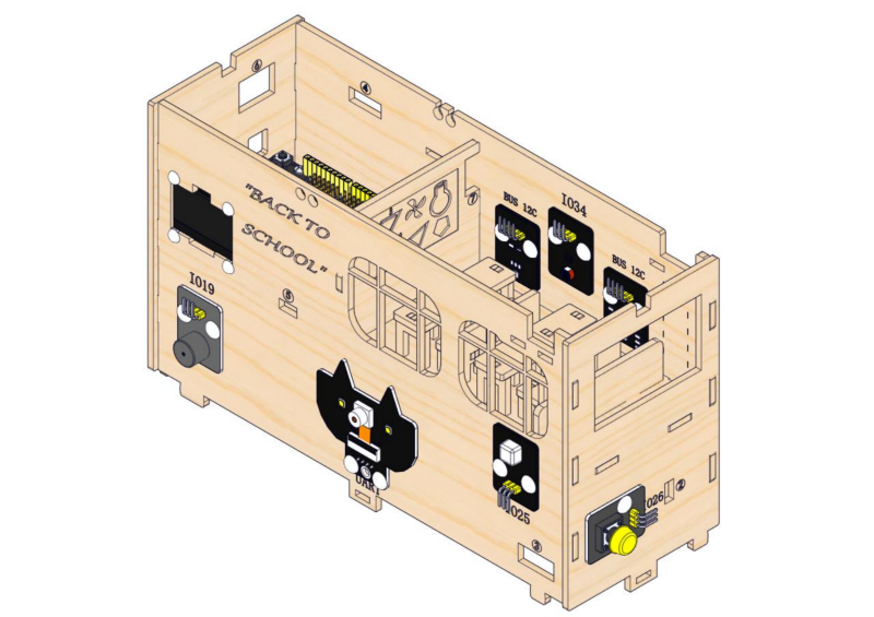
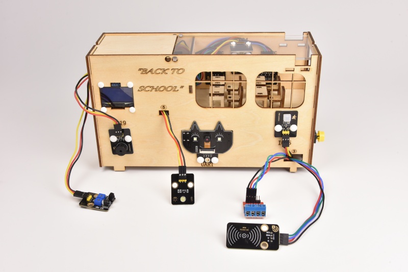
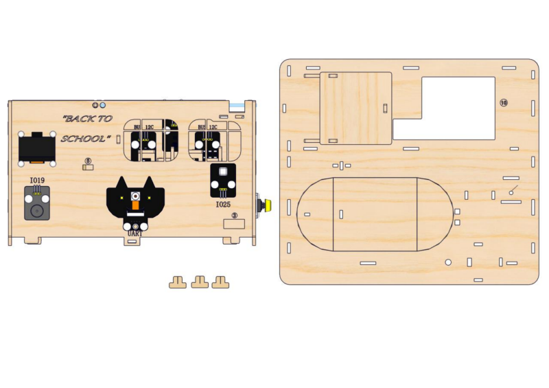
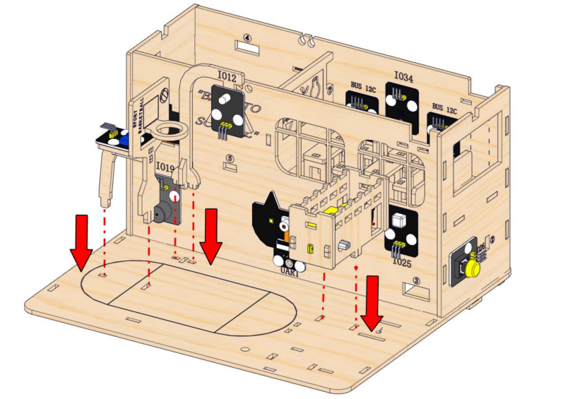
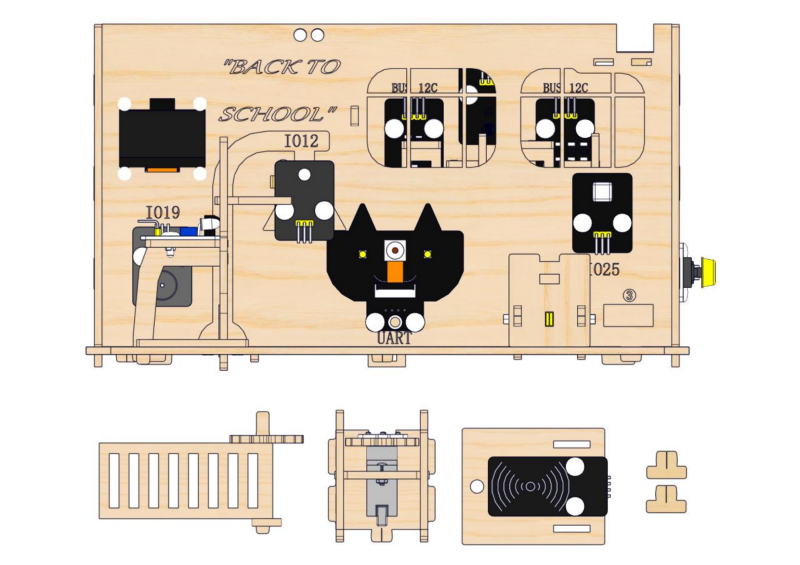
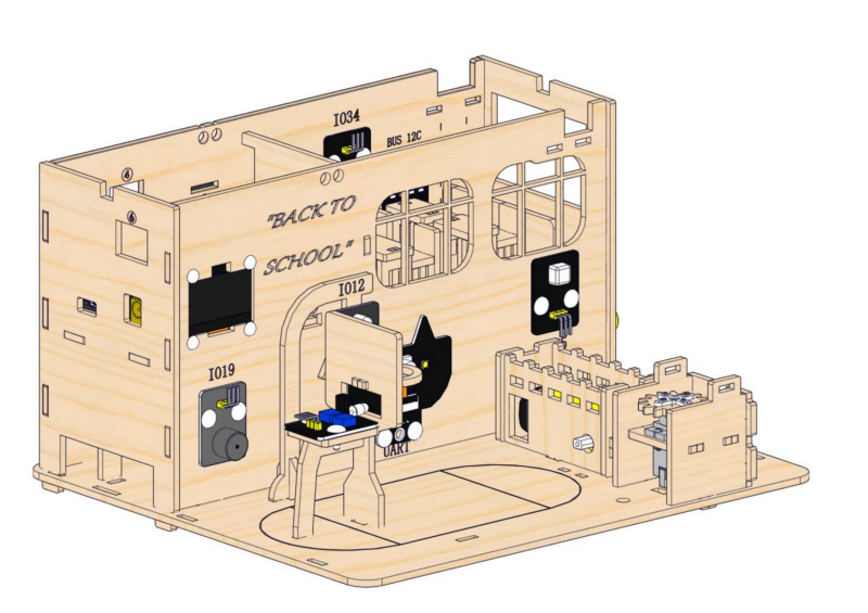
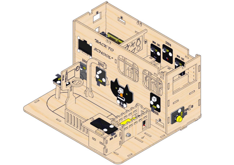
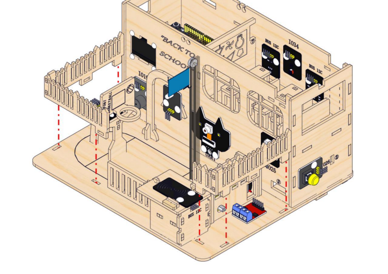
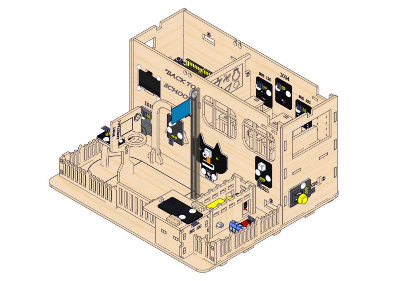
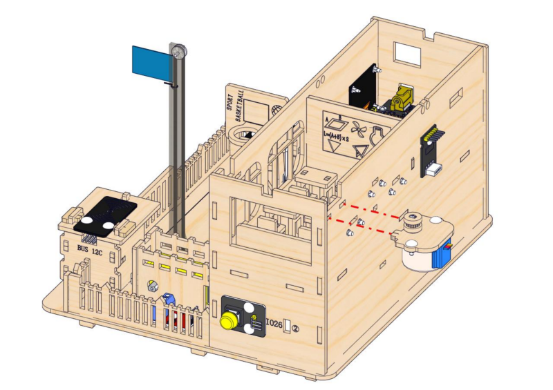
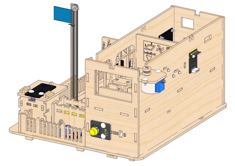
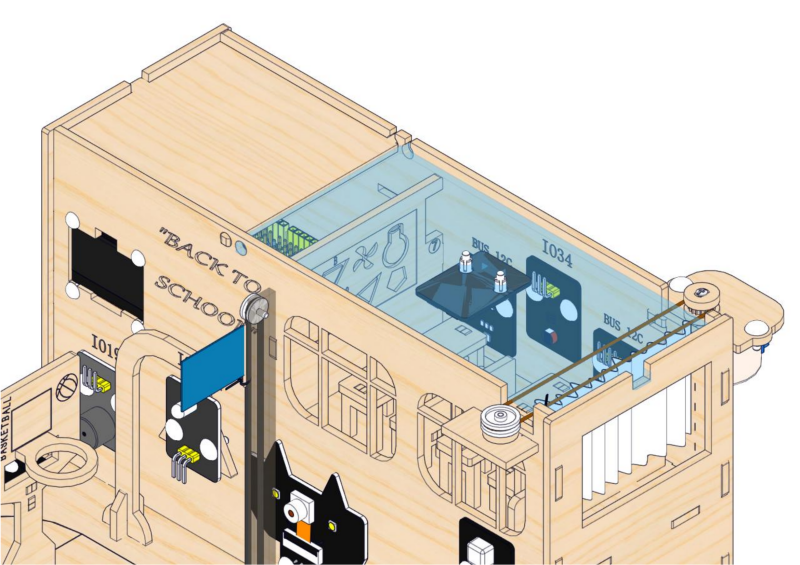
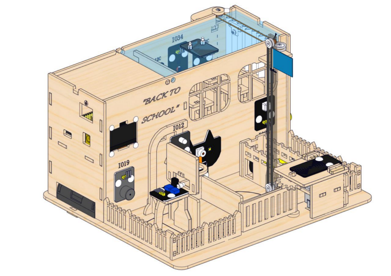
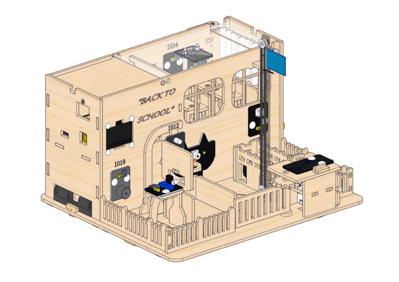
⚠Note: After wire up the above sensors and modules, it is as shown below.
2.2 Playground
1. Construction of Playground Facilities
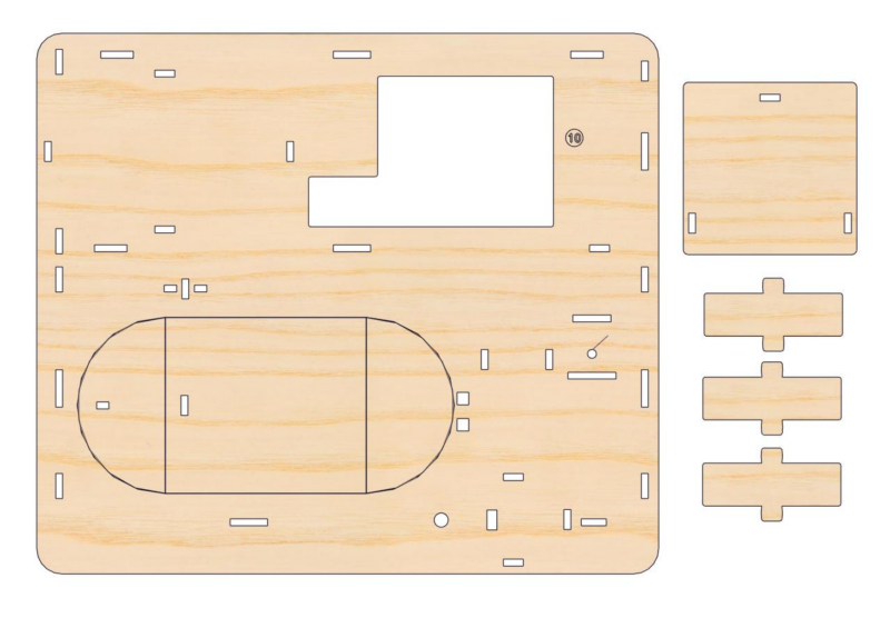
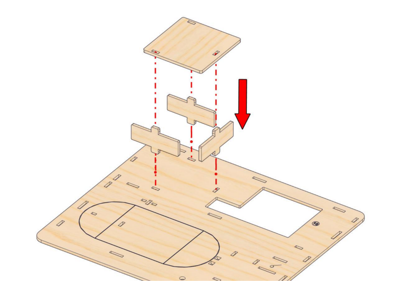
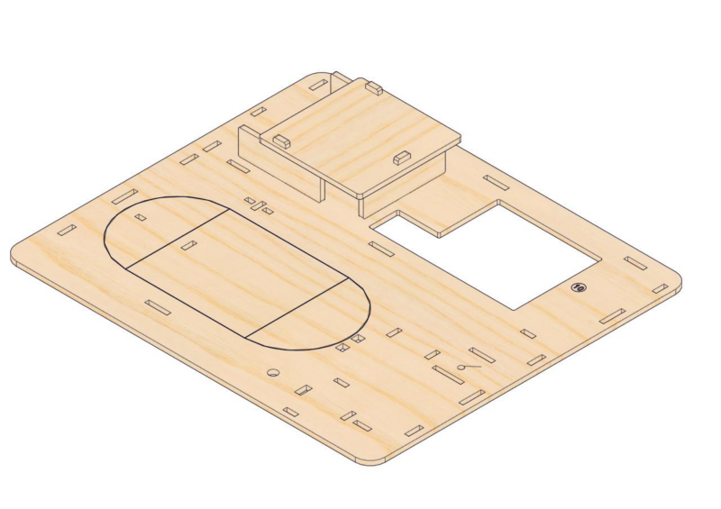
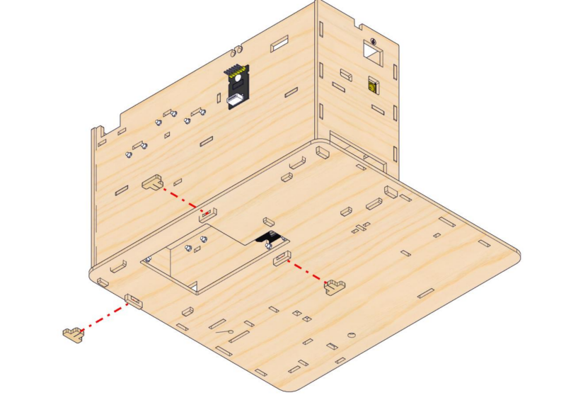
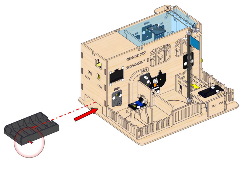
Step 9: Build the battery holder slot
9.1
Required parts
9.2
Step 10: Mount the teaching building and its base
10.1
10.2
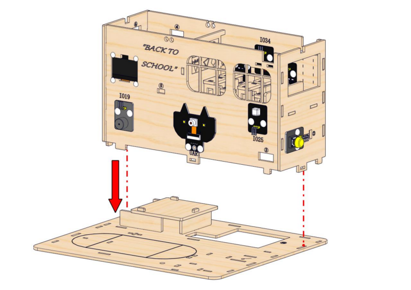
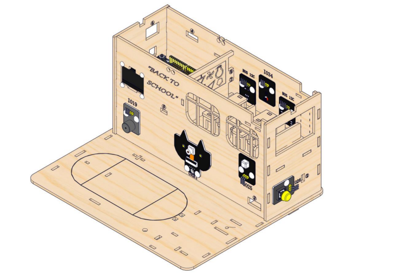
10.3
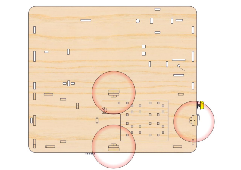
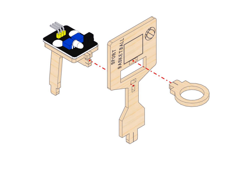
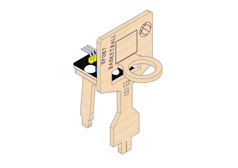
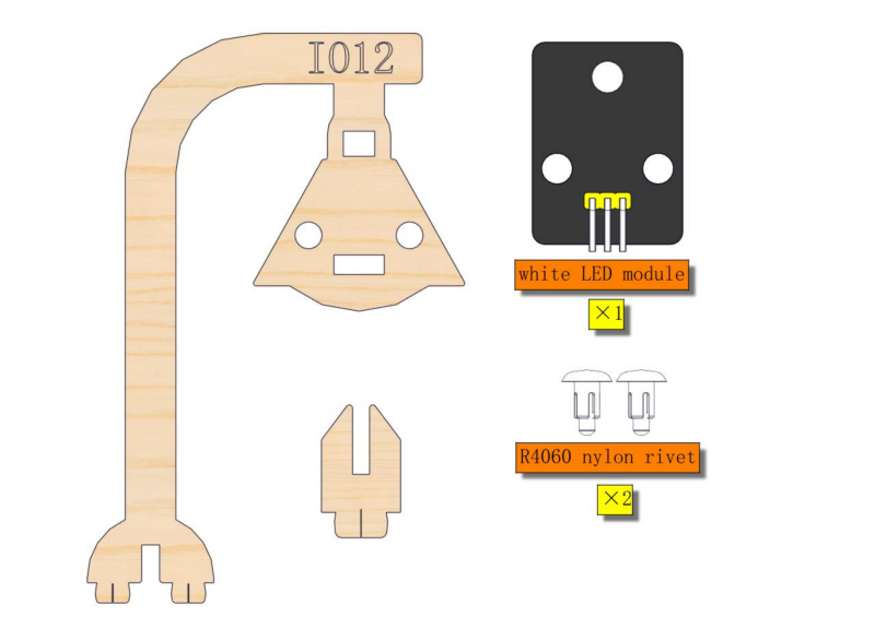
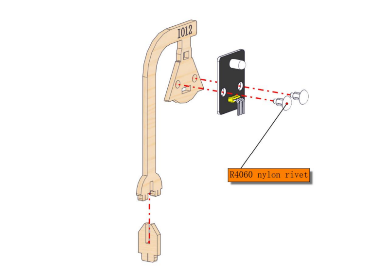
Step 11:Install the basket and obstacle avoidance sensor
11.1
Required parts
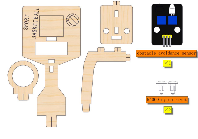
11.2
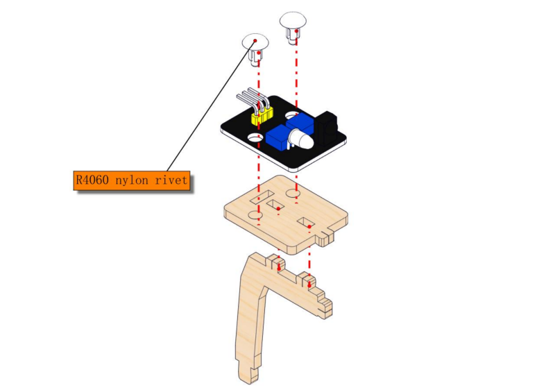
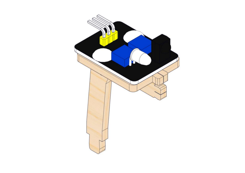
11.3
Step 12: Assemble street lamp
12.1
Required parts
12.2
Step 13: Assemble flag lifting platform
13.1
Required parts
13.2
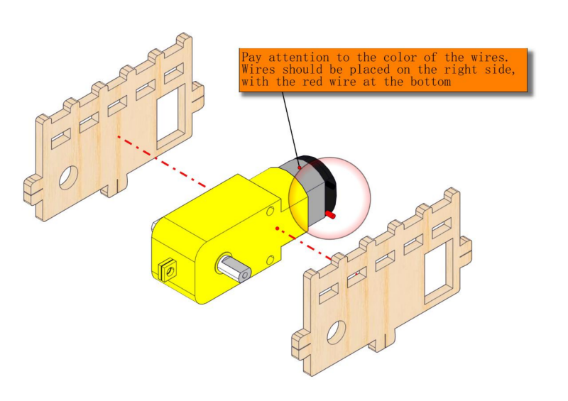
Pay attention to the color of the wires. Wires should be placed on the right side, with the red wire at the bottom. Note to pass wires through the rectangular hole.
13.3
Step 14: Mount playground facilities
14.1
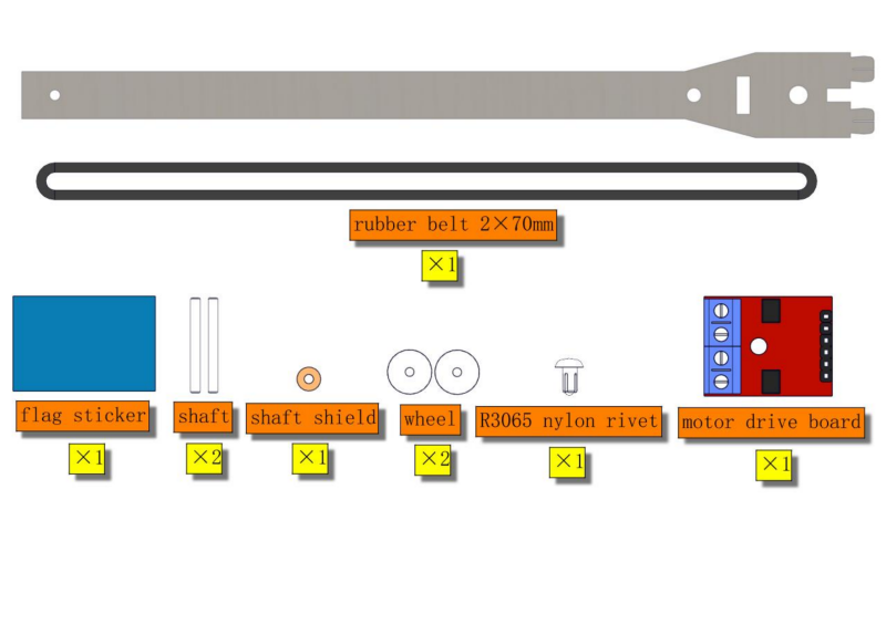
Required parts
14.2
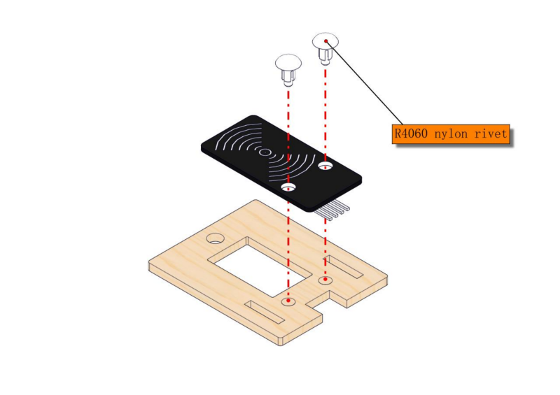
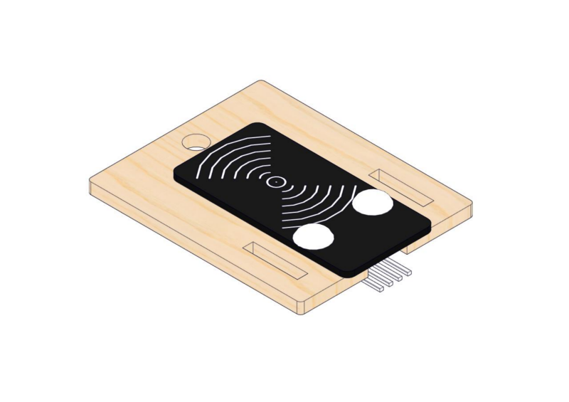
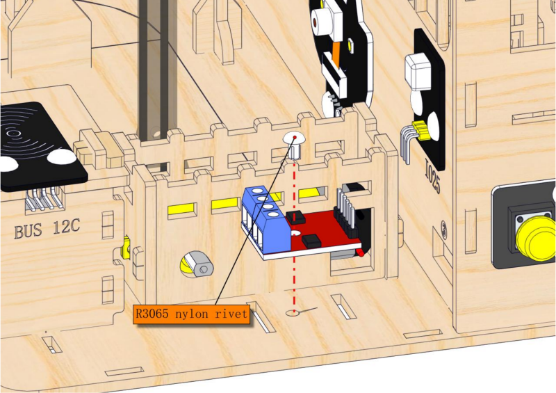
Step 15: Build the access control system
15.1
Required parts
15.2
15.3
15.4
15.5
15.6
15.7
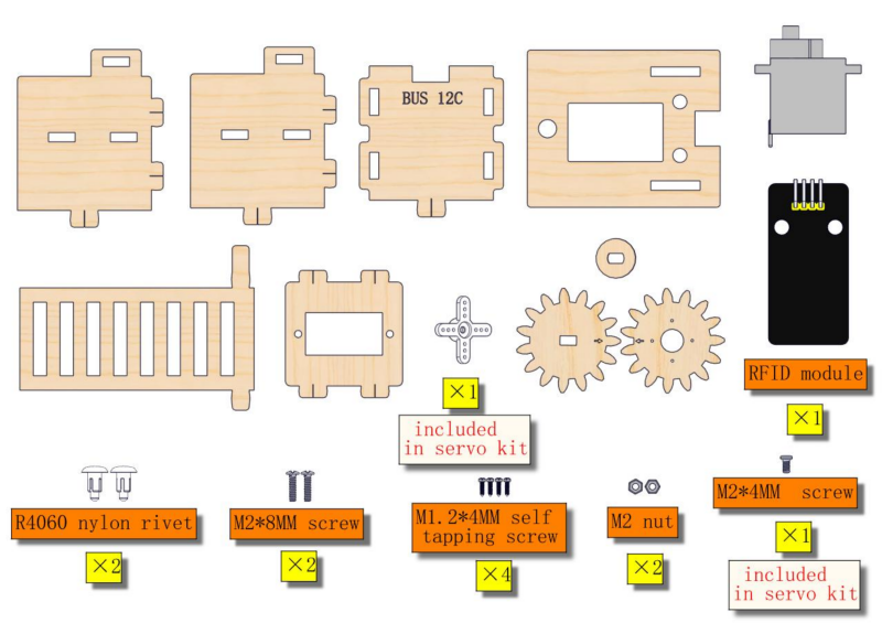
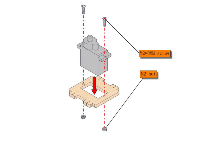
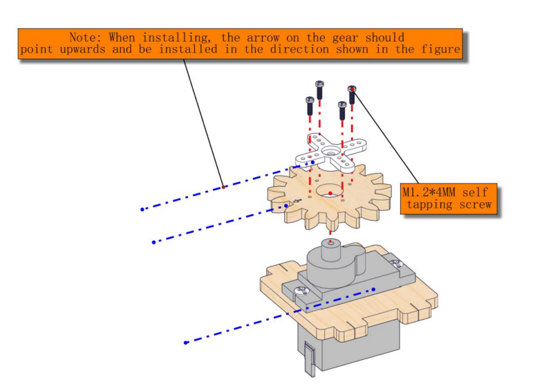
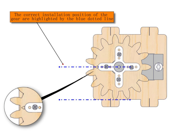
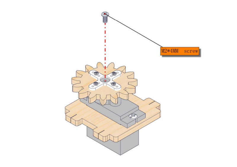
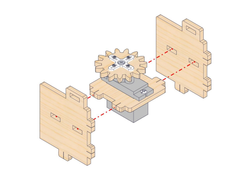
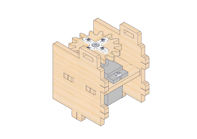
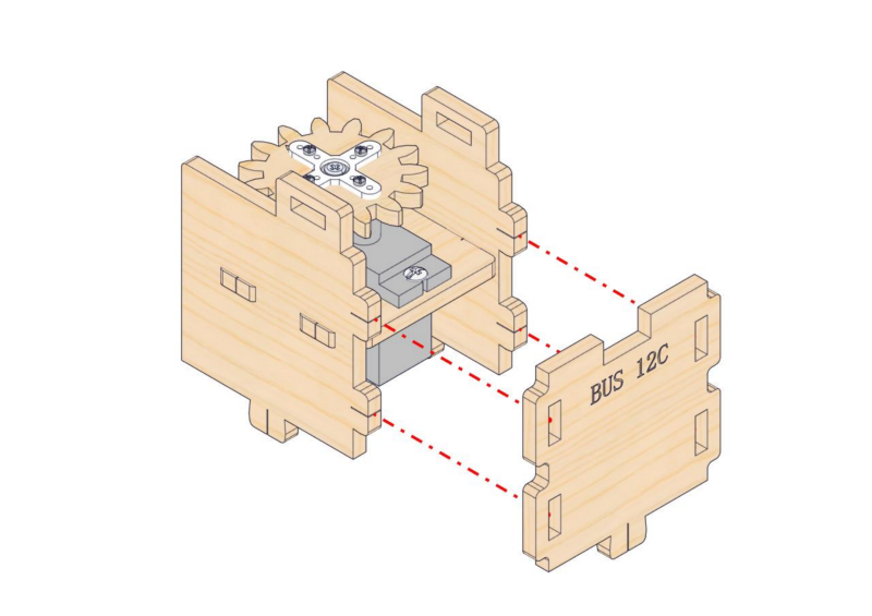
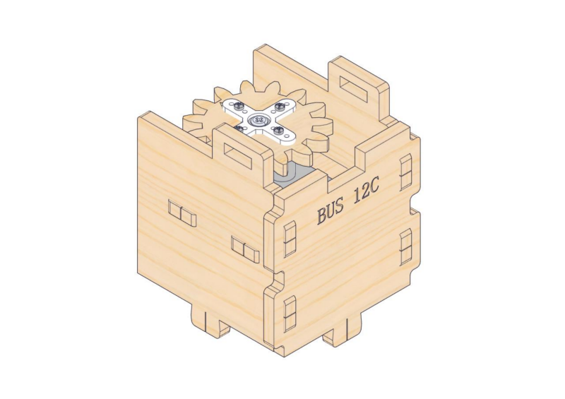
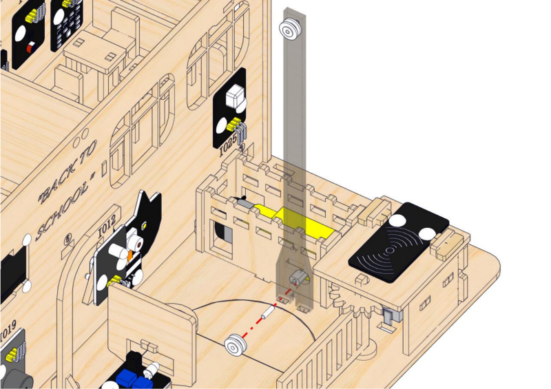
Step 16: Assemble the access control system
16.1
Required parts
16.2
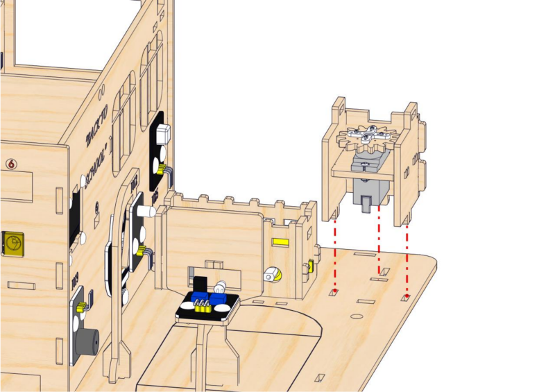
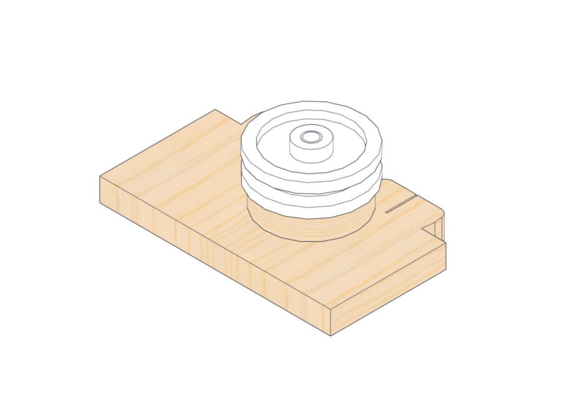
⚠️ Note: Before installing the servo onto the base board, servo wires need to be inserted through the rectangular hole on the base board.
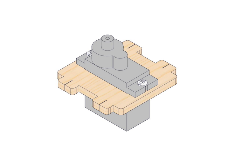
16.3

16.4
16.5
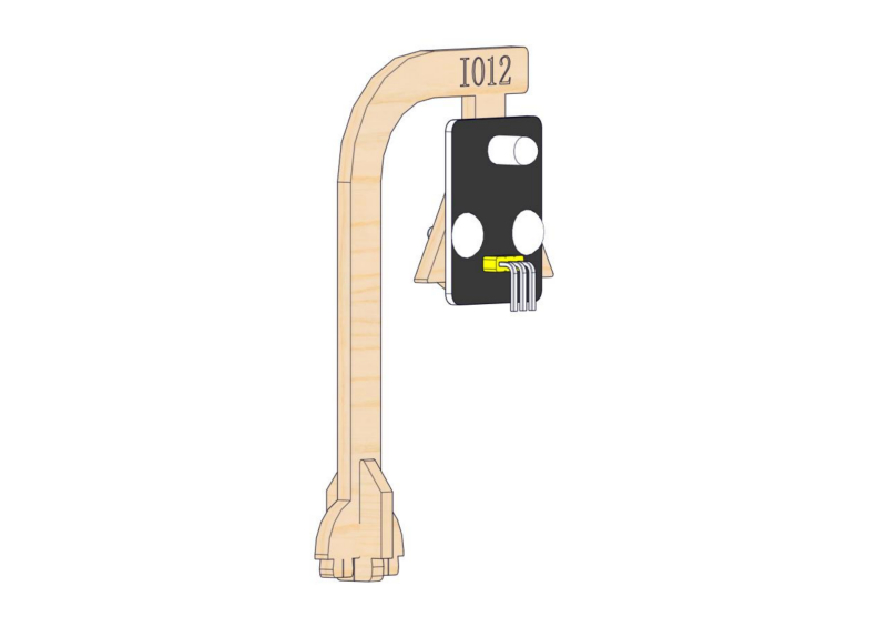
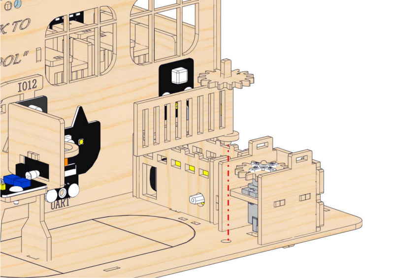
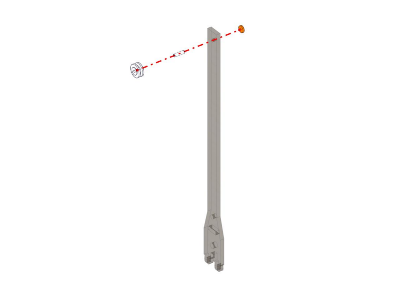
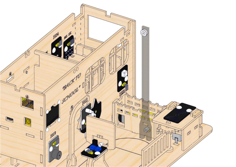
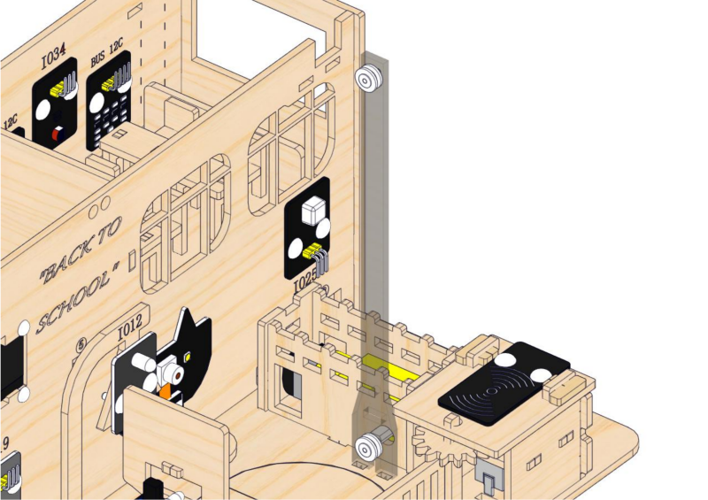
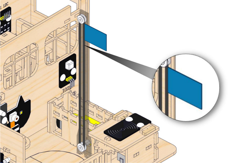
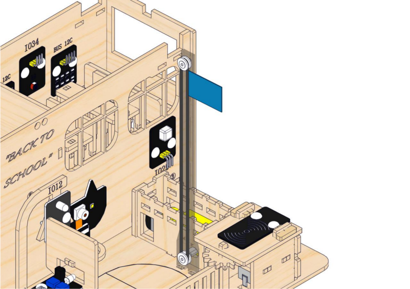
Step 17: Install the flagpole of the platform
17.1
Required parts
⚠ATTENTION: Acrylic flagpole is packaged separately. It is recommended to remove its protective films.
17.2
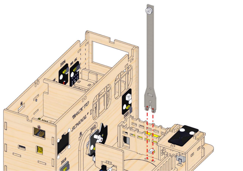
17.3
17.4
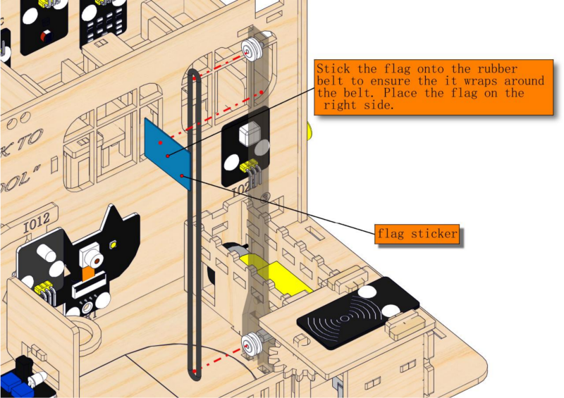
17.5
2. Wiring of Playground Facilities
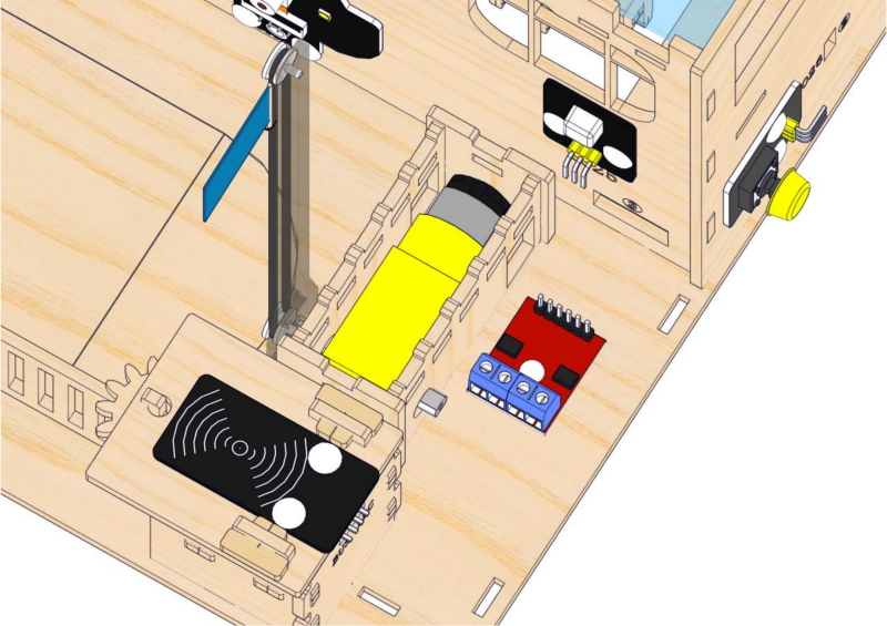
Step 18: Wire up the motor drive board and servo
18.1
Please connect the wires in the following order. When connecting, please distinguish the color of the wires.
# |
Module |
Wire |
Corresponding pin |
|---|---|---|---|
1 |
servo |
/ |
ESP32 board: IO32 |
2 |
motor |
/ |
motor drive board: blue terminal |
18.2
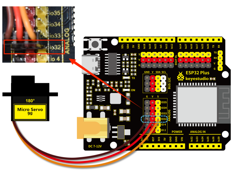
Connect the module to the ESP32 main control board via the wire as shown in the diagram.
Module |
Wire |
Corresponding pin |
|---|---|---|
servo |
/ |
IO32 |
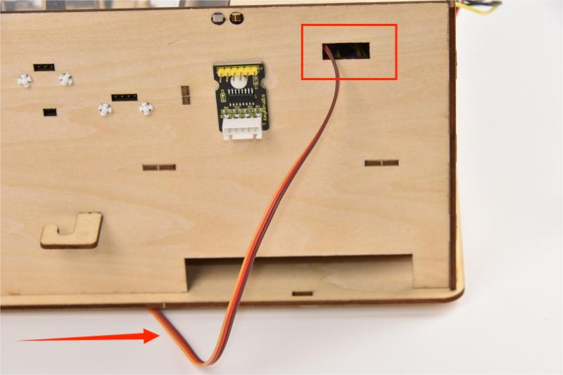
Wind servo wires from the bottom to the back of the building and pass it through Hole 4.
When connecting to the main board, please distinguish the color of the wires.
Module |
Wire color |
ESP32 board pin |
|---|---|---|
V |
Red wire |
V |
G |
Brown wire |
G |
S |
Yellow wire |
IO32 |
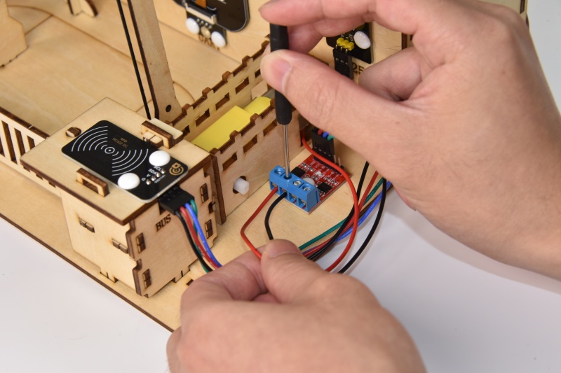
18.3
Connect the module to the ESP32 main control board via the wire as shown in the diagram.
Module |
Wire |
Corresponding pin |
|---|---|---|
motor |
/ |
motor drive board: blue terminal |

2.3 Fences and Classroom Equipment
1. Fences
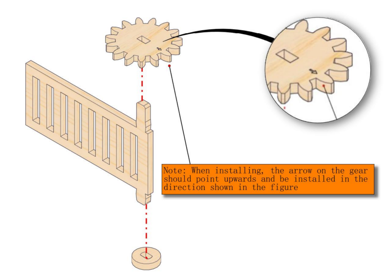
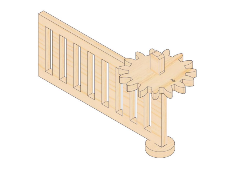
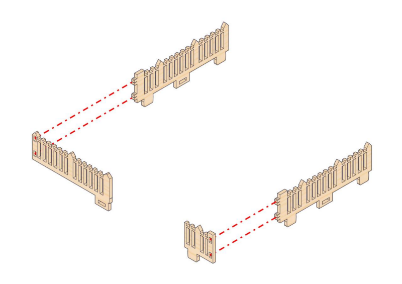
Step 19: Build the school fence
19.1
Required parts
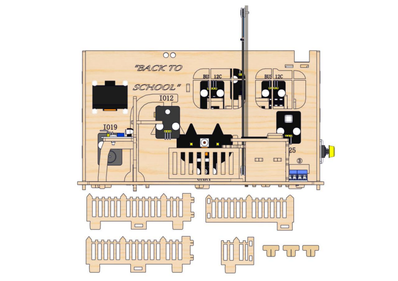
19.2
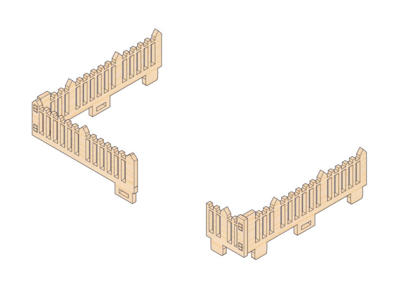
19.3
2. Classroom Equipment
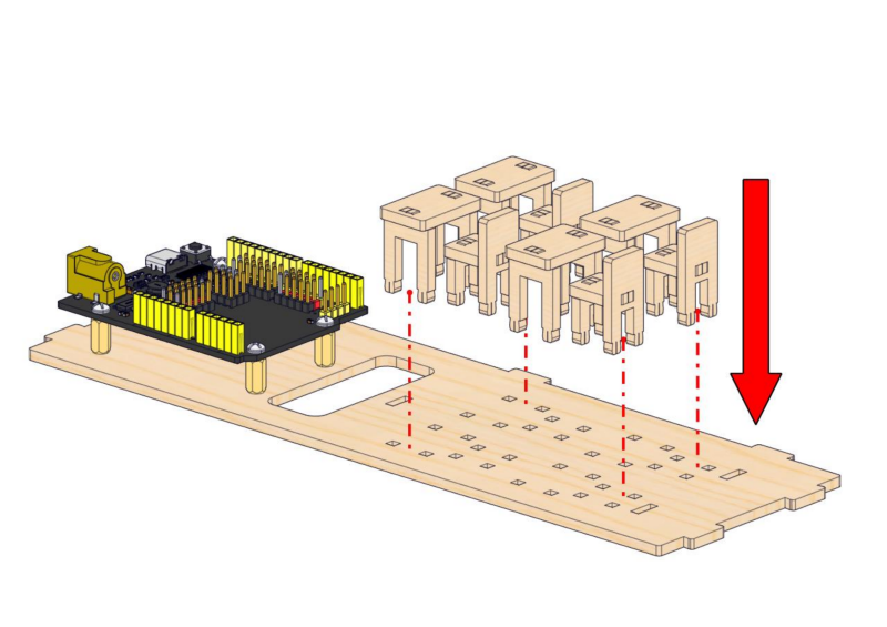
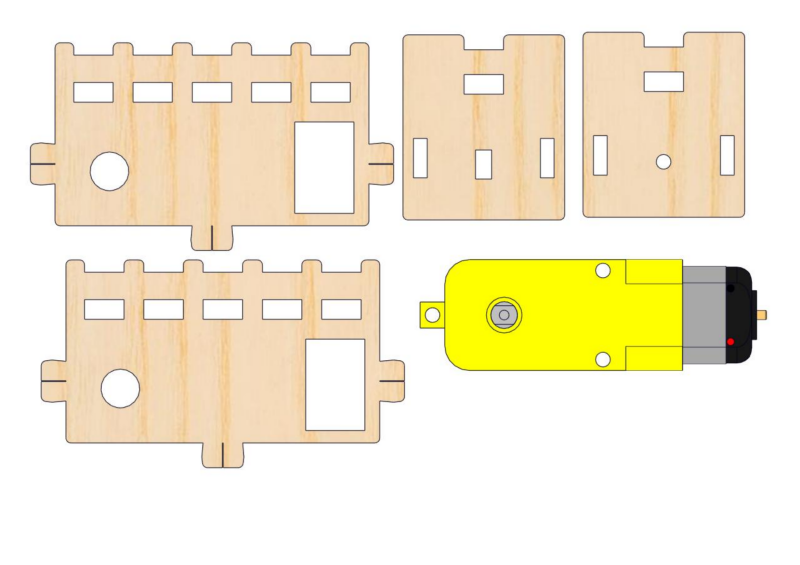
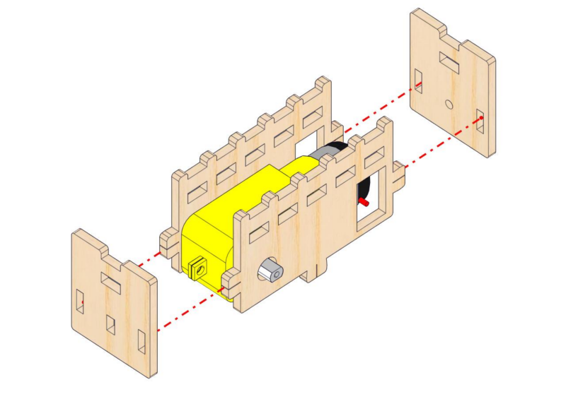
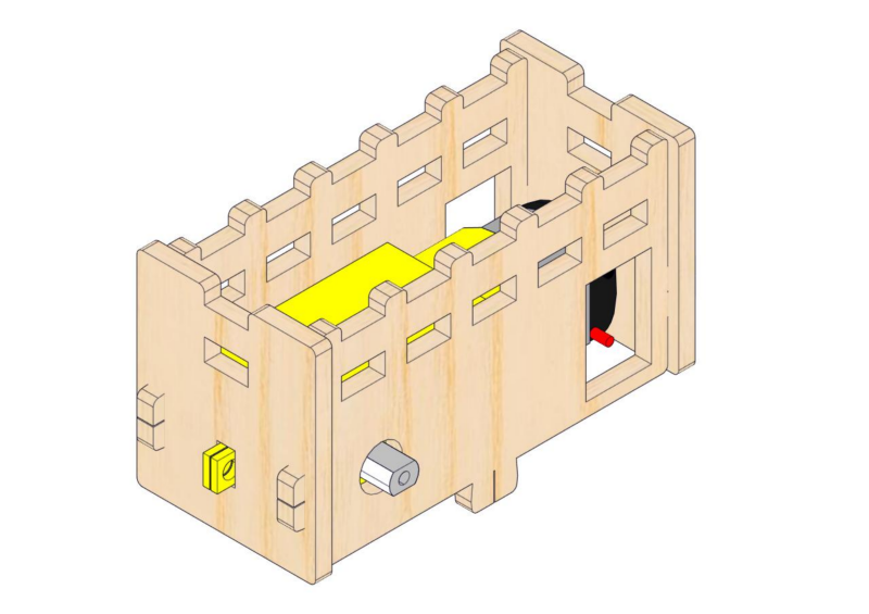
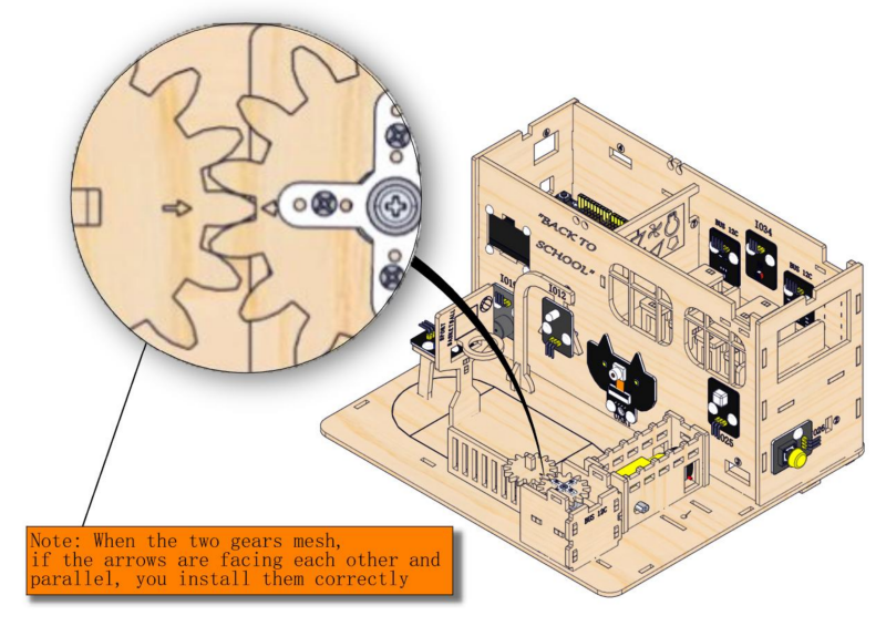
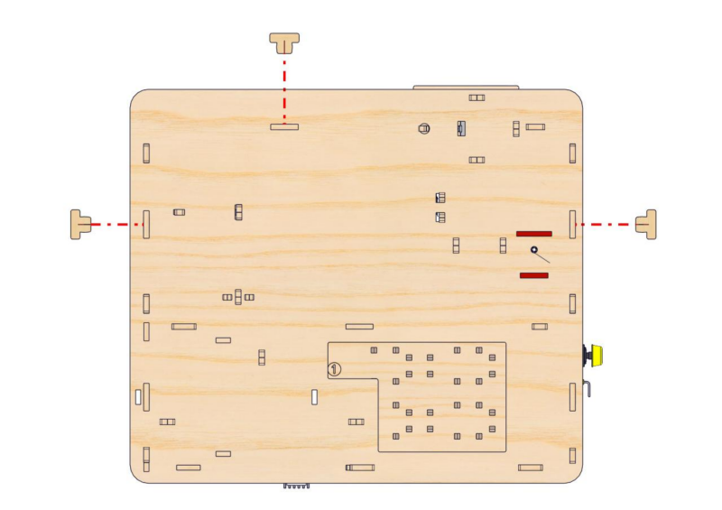
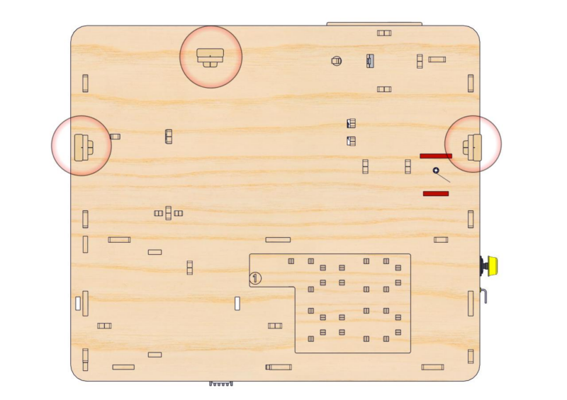
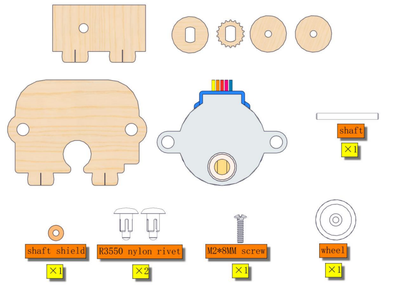
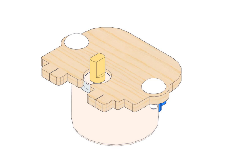
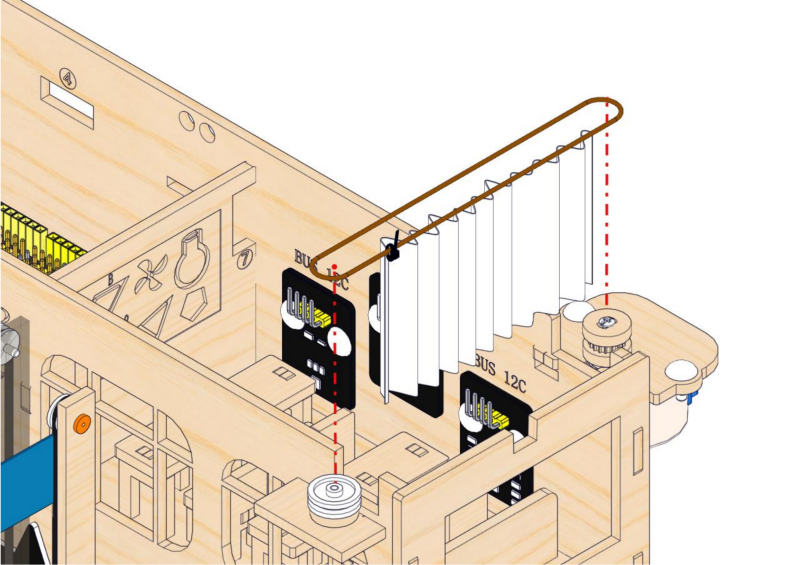
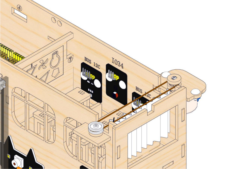
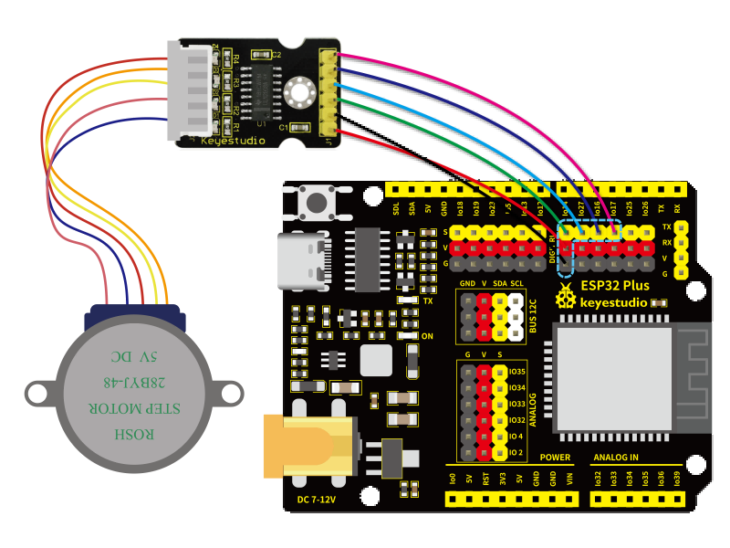
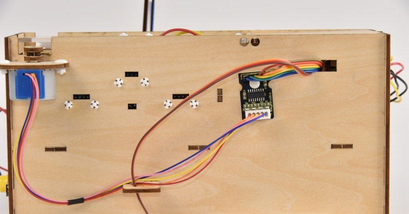
Step 20: Install stepper motor drive system
20.1
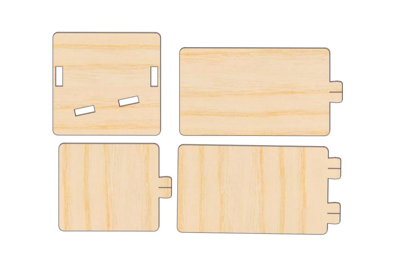
Required parts
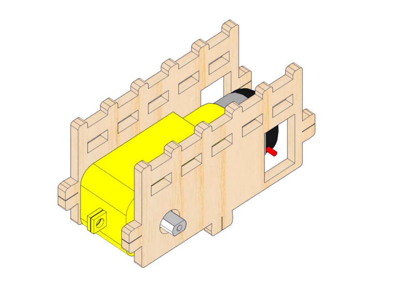
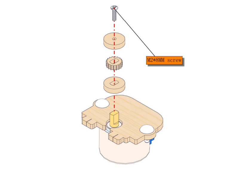
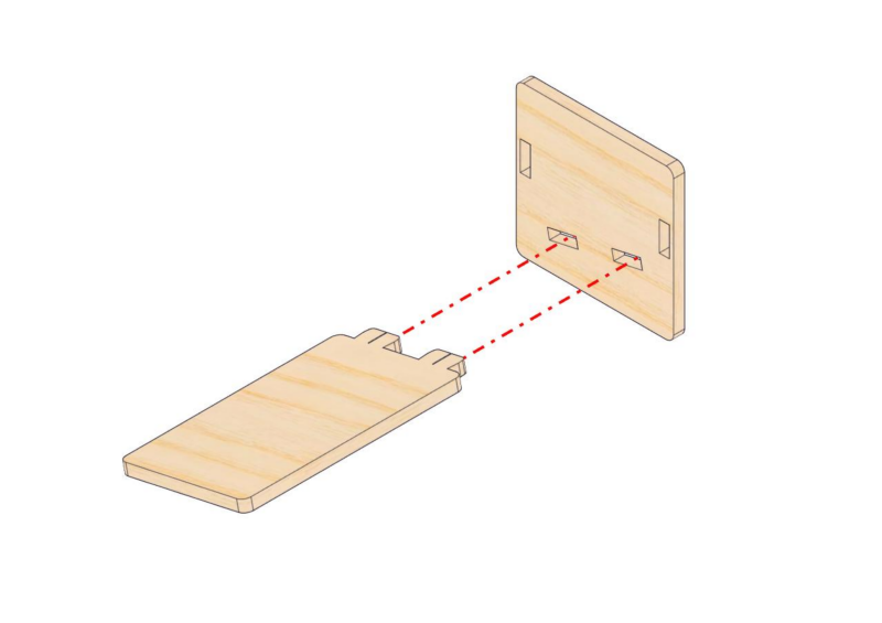
20.2
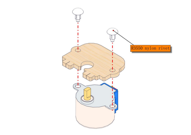
20.3
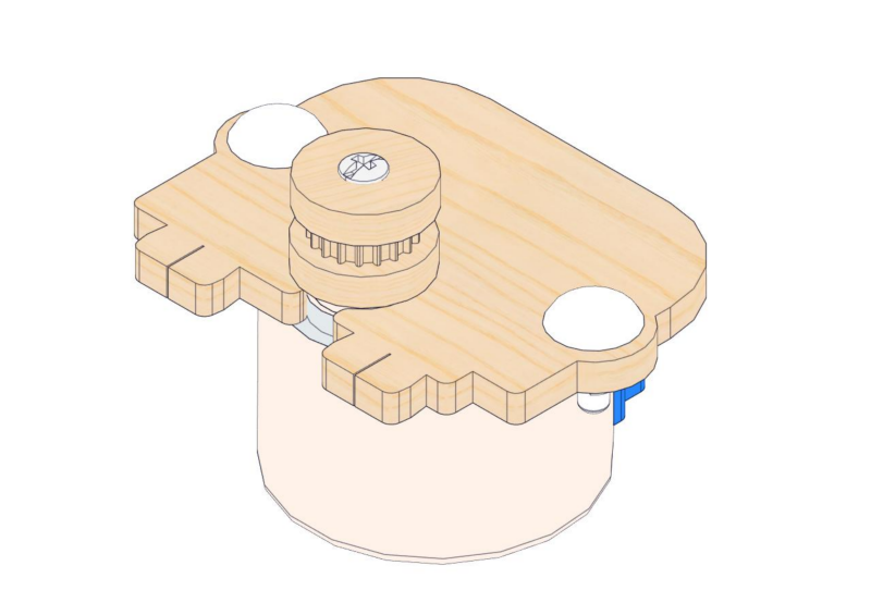
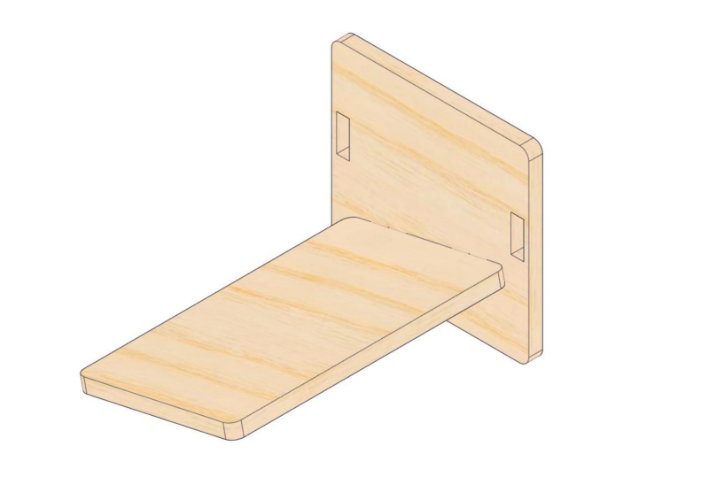
20.4
20.5
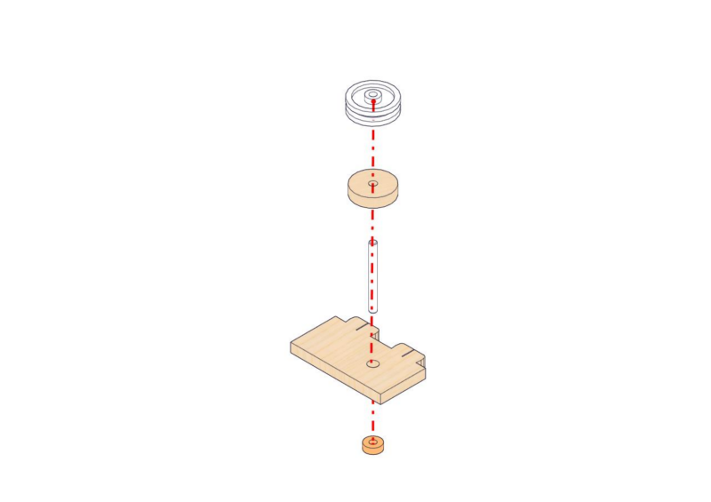
20.6
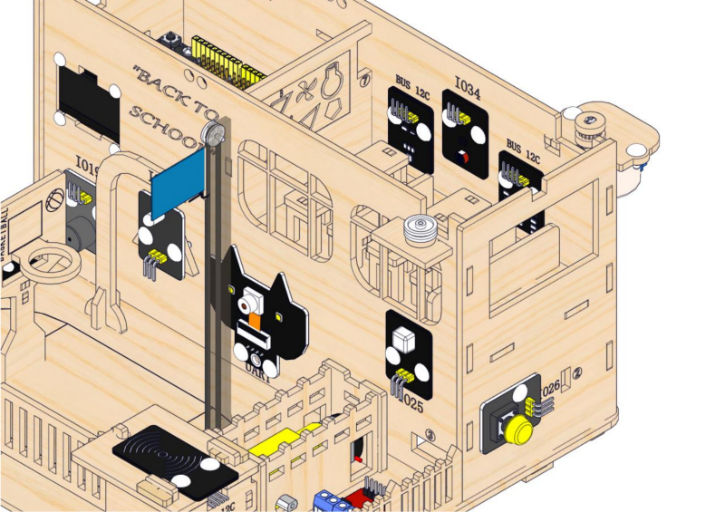
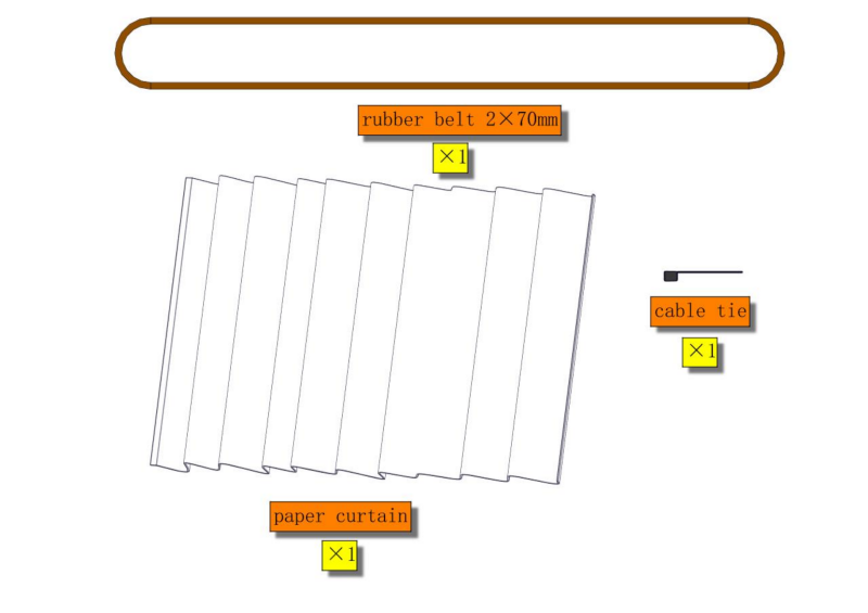
Step 21: Put on the curtain
21.1
Required parts
21.2
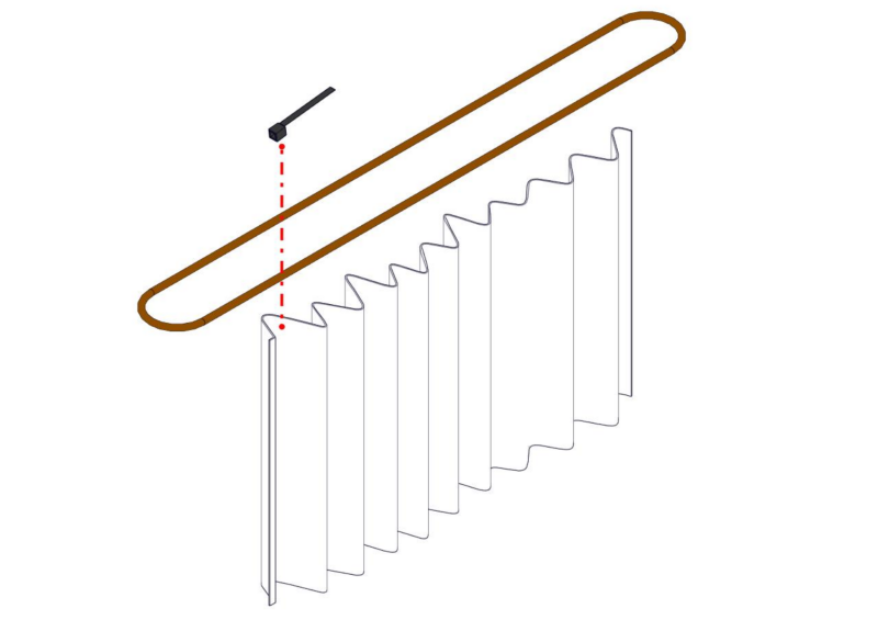

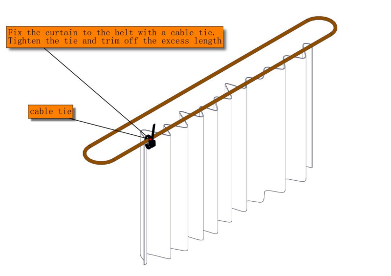

21.3
21.3
Stick the curtain on the wall of the teaching building.
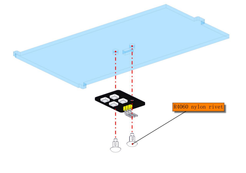
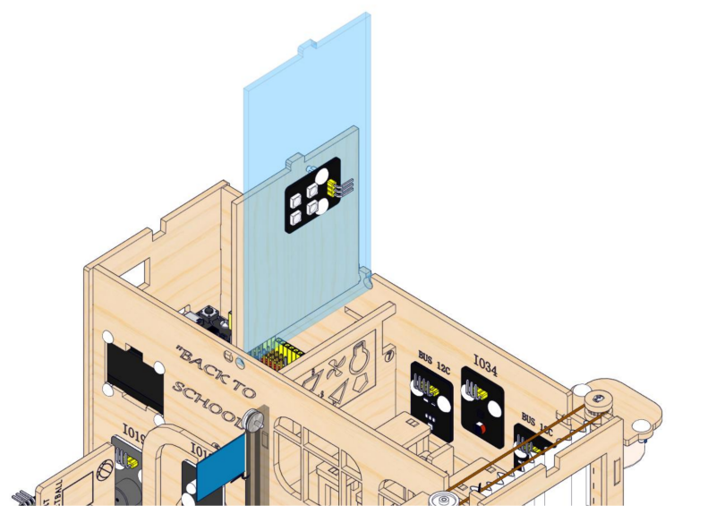
Step 22: Install RGB module
22.1
Required parts
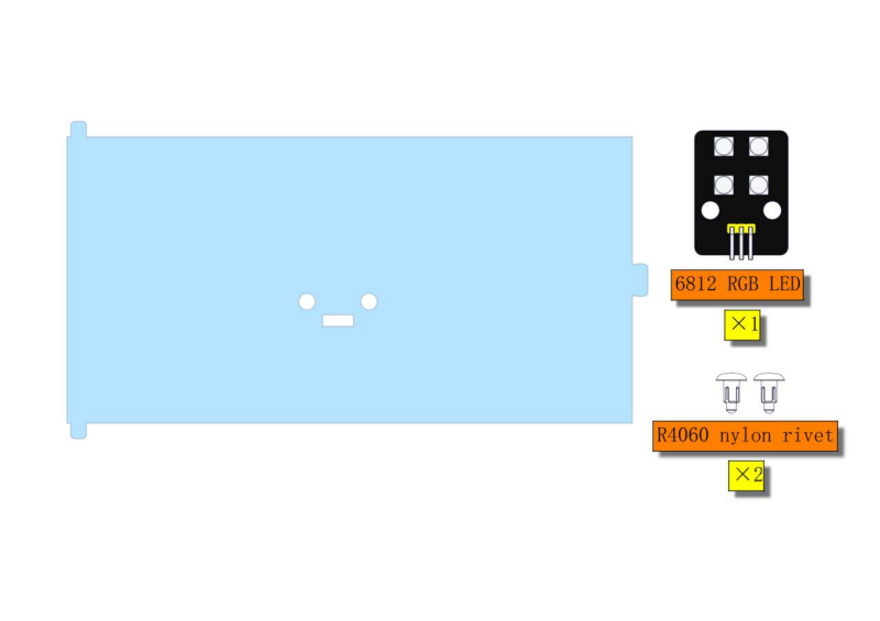
⚠ATTENTION: Acrylic ceiling is packaged separately. It is recommended to remove its protective films.

22.2
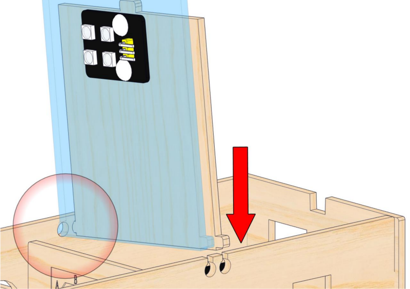
Step 23: Assemble the ceiling
23.1
Required parts
23.2
⚠ ATTENTION : First, install the ceiling into the two small round holes on the front wall of the teaching building, and then press the ceiling down vertically against the back wall.
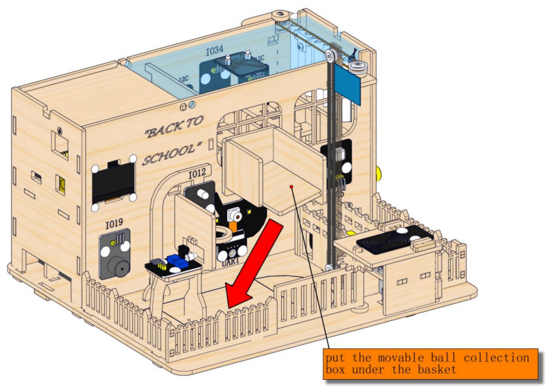
2.4 Ball Collection Box and Battery Holder
1. Ball Collection Box
Step 24: Make a movable ball collection box
24.1
Required parts
24.2
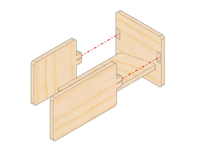
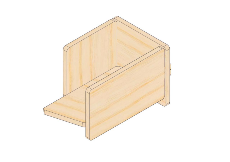
24.3
2. Battery Holder
Step 25: Add a wire hook and the battery holder
25.1
Required parts
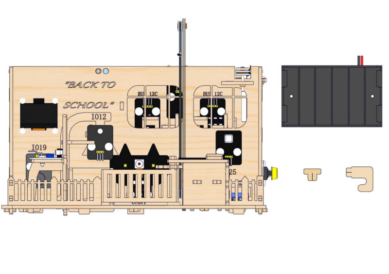
25.2
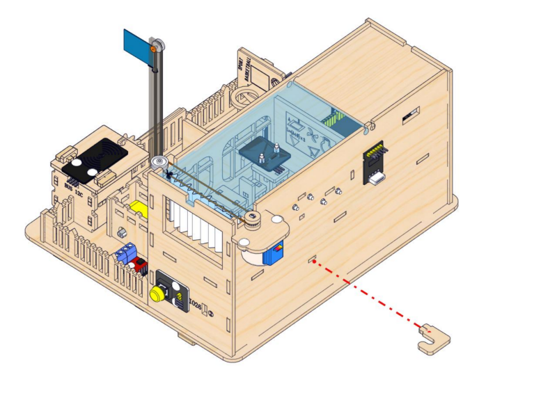
25.3
Connect the wires of the stepper motor to the stepper motor driver board, and arrange the wires of the servo and the stepper motor onto the hook
25.3
Completed !